Disclaimer #
All information contained in this document is exclusively for use within Microsoft Flight Simulator. The present document is not a manual for the real aircraft or any kind of training supplement and should not be used as such. SimWorks Studios Ltd and Pilatus Aircraft Ltd waive any responsibility for damages that may be caused from the use of this document in real aviation.
For any enquiries, please contact SimWorks Studios Ltd. between 7:00 to 15:00 GMT at info@simworksstudios.com.
For support, please visit our website at: https://simworksstudios.com/knowledge-base.html
1. Introduction #
1.1 About the SWS PC-12/47 #
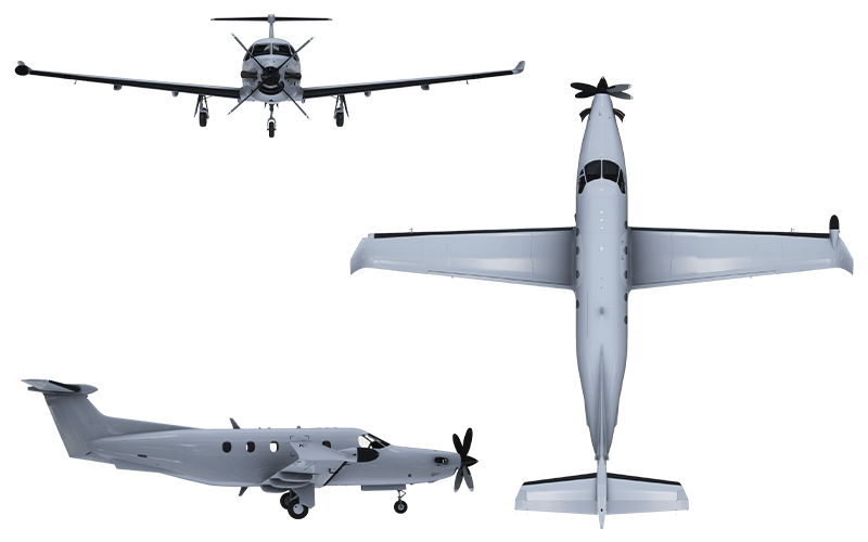
The SWS PC-12/47 is a representation of the iconic PC-12 Series 10 manufactured by Pilatus Aircraft Ltd. of Switzerland. With more than 2,000 aircraft produced since its first flight in 1991, the PC-12 has proven itself as a versatile and reliable aircraft, capable of operating out of short, unprepared airstrips just as well as out of paved runways. The aircraft fulfils a variety of roles: executive transport, commuter, cargo transport and air ambulance.
By bringing together the expertise of the manufacturer, aircraft operators and pilots, we have tried to provide the full PC-12 experience — from flight handling and sounds to the different interior configurations.
1.2 Acknowledgements #
The SWS PC-12 was created under licence from Pilatus Aircraft Ltd. All included liveries, logos and trademarks were created under licence from their respective operators.
SimWorks Studios Ltd. holds an exclusive licence for the creation of liveries of Fly7 Executive Aviation for the SWS PC-12 for Microsoft Flight Simulator.
1.3 Development Team #
Development of the aircraft has gone through numerous iterations. SWS team members contributed in multiple areas to complete the aircraft. In no particular order:
- Nawfal Benbennasser: Base aircraft model
- Elias Strikos: 3D model refinement, interior textures, exterior textures
- Matt Wynn: Interior textures, exterior textures, liveries
- Evripides Efthymiou: Avionics programming
- Alexander Losev: Avionics programming
- Paul Frimston: Flight dynamics
- Alex Vletsas: 3D model refinement, animations, systems programming, engine modelling
- SimAcoustics: Sound recording and mixing
- Akis Karagiorgos: Vector graphics
1.4 Special Thanks #
We would like to extend our sincerest thanks to all the people that had to bear with us during the long development process of the SWS PC-12. Starting with our families and friends, special thanks go to:
- Fly7 Executive Aviation, Yves Roch (CEO) and Thomas Goncalves (Fly7 Community) — for providing us a flight in the aircraft, sound recordings and a week of simulator time and instruction on the PC-12, all undertaken at the Fly7 Training Center in Lausanne, Switzerland.
- MS Aviation South Africa — for reaching out very early in the project, providing a wealth of reference material and advice for the creation of the aircraft.
- Tradewind Aviation — for providing us with reference material to faithfully recreate their aircraft livery.
- Revue Thommen AG — for providing us with the manual to the DC20 Chronograph and helping us make an authentic rendition of it.
- Brandon Hostetter — for his diligent testing and feedback in refining the flight model & systems simulation of the aircraft. Brandon helped us delve into intricacies of the Legacy PC-12 that we otherwise couldn’t have known.
- Raul Morales (FSReborn) — Raul has been a “silent contributor” during the development, as we exchanged knowledge and worked together for the betterment of our turboprop aircraft. A lot of back and forth has helped both our businesses and products and we intend to keep it that way!
- Dr. Evangelos Vaos — for providing his insight and advice on several problems that occurred during the development and release of the SWS PC-12.
1.5 Features #
Any items marked with an asterisk (*) are subject to MSFS limitations in their respective area.
Exterior Model #
- Accurate riveting and high-resolution stencils
- 4-bladed and 5-bladed propellers
- Custom animations: trailing link landing gear, custom nose wheel steering, stabilator trim, engine bypass door, chocks, pitot and AoA vane covers, engine bay, tail interior, de-icing boots
- 8 liveries: White, OH-JEM, HB-FVA, OH-FUK, OH-DEN, OH-PBL (Fly7 Executive Aviation), N881TW (Tradewind Aviation), PH-ONE (Private)
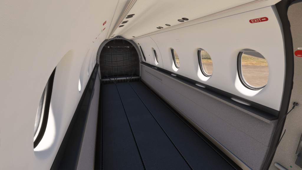
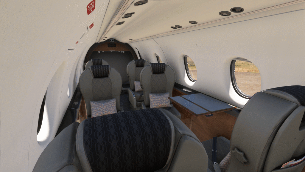
Interior Model #
- Fully functional cockpit
- Three interior configurations: Executive, Commuter and Cargo
- Working exits
- Fully working custom lighting
- GNS530/430; PMS & TDS (PC-only) GTN option
- Easily customisable for repainters
- Numerous custom animations: lavatory, armrests, drawers, sun visors, window shade, gust lock, passengers, cargo
Flight Model #
Created after spending a week in the real simulator with PC-12 instructors and with constant pilot feedback during development, the SWS PC-12 features:
- Realistic handling and performance
- Different 5-blade and 4-blade propeller simulation
- Custom engine simulation: correct ITT/altitude behaviour and limitations, correct Torque/Ng relationship, torque limiter, hot starts (no damage)
- Correct starter operation
- Torque effect on yaw*
- Nose-down approach attitude*
Systems #
- High-performance avionics using the MSFS Avionics Framework: Bendix/King EFIS50 with weather RADAR, Engine Instrument System, Thommen DC20 Chronograph, KAS927B
- Full electrical system with working circuit breakers
- Custom stall protection system: stall warning, stick shaker, stick pusher (including pusher ice & test modes)
- Custom nosewheel steering system with free-castering nosewheel when applying brakes
- Custom trim system with realistic timings*
- Custom de-icing system: realistic boot operation, individual windshield heating
- Custom air conditioning & heating system: adjustable temperatures based on real system limits, flow and volume based temperature distribution, insulation & open door effects
- Custom oxygen system, accounting for number of crew and passengers on board
- Custom warning system: fully working CAWS, numerous aural warnings, EGPWS system modes 1–3 and 5* and TAWS inhibition
- SWS Tablet: Weight & Balance, manual reader* & checklists, avionics swapping, feature controls (hide passengers/cargo, adjust volume)
*The walkaround feature is partially available through the preflight item “EXT LIGHTS CHECK” in the in-game checklists.
Sounds #
- High quality sounds recorded from three different aircraft
- 5-bladed and 4-bladed engine sounds
- Full aircraft sounds including starter, ignition, flap actuators, hydraulic pumps, warnings and electrical system components
- Full interior aircraft soundscape
- Correct sound insulation properties
1.6 Installation #
The SWS PC-12 is distributed either with the SWS Installer or via the Microsoft Flight Simulator Marketplace.
SWS Installer #
“Path too long” installation error: This can occur if the Community folder is located within the Appdata folder, as the final path of the installed files might exceed 256 characters. The simplest solution is to install the add-on in another location and create a symbolic link into your community folder.
Virus alerts: The downloaded package contains numerous elements that can be falsely flagged as malware. The installer’s own .exe file, as well as the numerous .xml, .html and JavaScript code files included with the aircraft can be flagged by antivirus software. The SWS PC-12 files and installer have been verified using online scanners such as VirusTotal and Internxt.
Flight Simulator Marketplace #
The GTN cockpit and Sky4Sim options of the product cannot be made available through the MSFS Marketplace due to platform limitations. PC users will be able to get the required mod files from the SWS website and install them manually. These options are not available for Xbox users.
1.7 Support #
In the event you encounter any issue with the aircraft, we recommend that you contact us on our support venues with the following information:
- What is the problem? (e.g. reds and chocks will flicker)
- What were you doing before the problem happened? (e.g. looking at the plane)
- Did you try running the plane alone in the community folder, with all other mods removed?
- If you did #3, did you encounter the problem again? What is the reproduction rate? (e.g. 2 out of 10 times)
- SWS Support page — Read the known issues or Contact Support
- SWS Discord server — Open a ticket at #official_support
1.8 Control Assignments #
All basic flight controls of the SWS PC-12 are assigned to default MSFS events. A special case is the condition lever, which can be mapped to either the default Condition Lever or Mixture lever assignments in the MSFS controls screen. The assignments have been modified via custom code to work the same and avoid accidental engine cut-offs or light-ups.
The plane also makes use of custom variables, listed in a separate document available on the SWS PC-12 page under “Free Extras”. These variables can be used by power users to control non-default functions of the aircraft. The variable list and names are likely to change as the aircraft evolves.
1.9 Development Roadmap #
The SWS PC-12 will continue to be updated with more features in the near future. Some of the upcoming features were not possible until very late in the development cycle, while others were until very recently beyond our technical reach.
Free Updates #
- EFIS50 Flight Plan mode
- EFIS50 Composite mode
Planned Expansions #
While the present add-on is a very extensive simulation of the real PC-12/47, failures were omitted from the package. This is because the majority of MSFS users do not wish to experience failures since they may overwhelm them, cause problems with secondary software (e.g. interrupting VATSIM traffic), or detract from a limited flying time.
We are therefore planning a payware expansion that will include deeper simulation of the various aircraft subsystems and associated failures. The approach we are taking is different from the typical “aircraft mechanic simulator” model — we want to focus on the flying part. Planned improvements include:
- Custom Fuel Control Unit with improved simulation of the various inputs
- Improved fuel system simulation
- Deeper electrical system simulation
- Organic manifestation of problems and failures based on component wear and abuse
- Realistic maintenance feedback — no magical “know-it-all” tablet listing
2. Quickstart Guide #
This section aims to supplement the in-game checklists and prepare you for some of the new behaviours you will experience with the SWS PC-12.
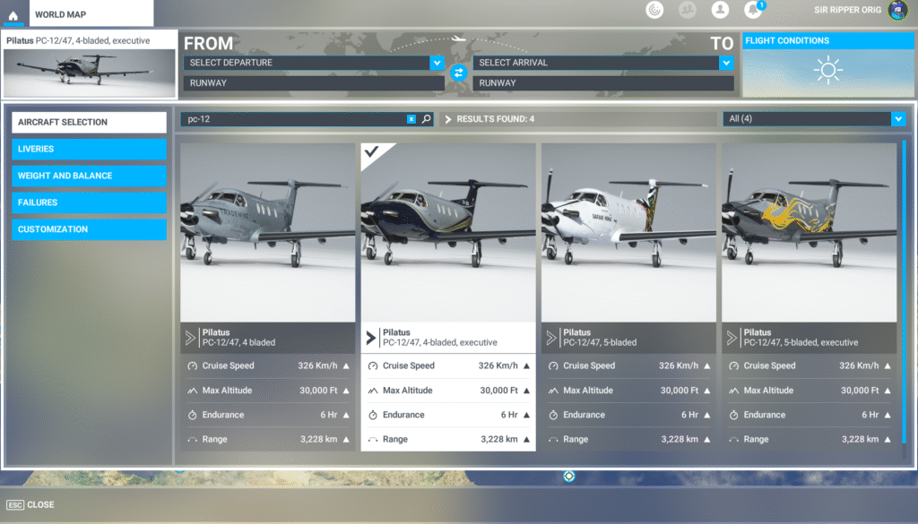
2.1 Selecting Aircraft Variations #
The SWS PC-12 comes with two exterior and three interior models that can be found in the AIRCRAFT SELECTION option. Because different flight models were required for the Executive and Cargo/Commuter versions, the Executive versions appear as different aircraft. Interior configurations can be differentiated by the aircraft title shown on the thumbnails.
Available options are:
- 4-Bladed: Cargo or Commuter cabin with 4-bladed engine
- 4-Bladed, Executive: Executive cabin configuration with 4-bladed engine
- 5-Bladed: Cargo or Commuter cabin with 5-bladed engine
- 5-Bladed, Executive: Executive cabin configuration with 5-bladed engine
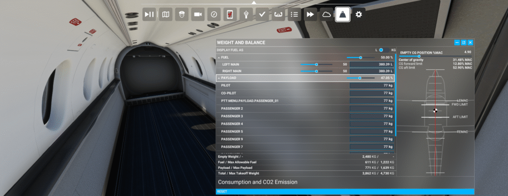
2.2 Weight and Balance #
The SWS PC-12 can be loaded using the in-game “Weight and Balance” menu. This will allow you to set the cargo and passenger weights, which will automatically make them appear in the cabin.
If adjusting the weight using the sliders, always check to make sure that your Center of Gravity is within the limits of 12.8% to 52.9%. Exceeding these limits will put the plane out of balance and can result in uncontrolled flight behaviour.
2.3 Gust Lock & Sun Shade #
When the aircraft is cold & dark and the gust lock is installed, a large clickable area will occupy the forward windshield. Clicking this area allows you to install or remove the cockpit sun shade. When the sun shade is installed, the visors will automatically move down to support it.
The sunshade can be removed by clicking on the forward windshield area or removing the gust lock from the pilot’s yoke. The visors will not retract automatically when the sun shade is removed. To quickly retract the visors, click at their pivot on the outboard corner of each glareshield window.
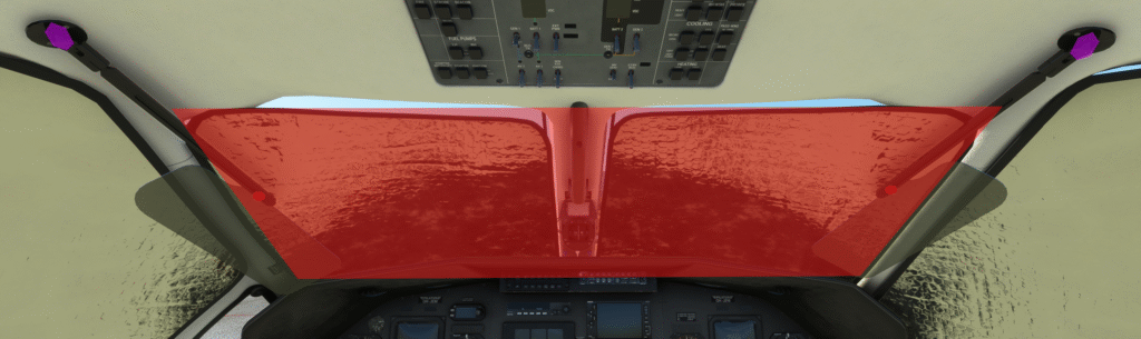
The SWS PC-12 also features a working gust lock. When the plane is started cold & dark, the gust lock will be on the yoke. When starting in any other state, the gust lock can be found on the left cockpit wall, next to the pilot’s seat. When the gust lock is inserted into the yoke’s base, the aircraft controls can no longer be moved.
To insert the gust lock:
- Click on the stowed gust lock on the left cockpit wall. Doing so will put it “in your hand”.
- A new clickspot will become available above the pilot’s yoke and in front of the HSI. Make sure the yoke is centred and insert the gust lock by clicking this area. This will lock all flight controls in a centred position.
To remove the gust lock:
- Click above the pilot’s yoke to remove it from the controls. This will put the gust lock “in your hand”.
- Find the stow on the left cockpit wall. Click on the stow area to secure the gust lock.
If you do not stow the gust lock it will remain “in hand”. This allows you to insert it by accident and jam your controls — this behaviour is intentional and is designed to ensure that users learn the correct procedure for stowing and unstowing the gust lock.
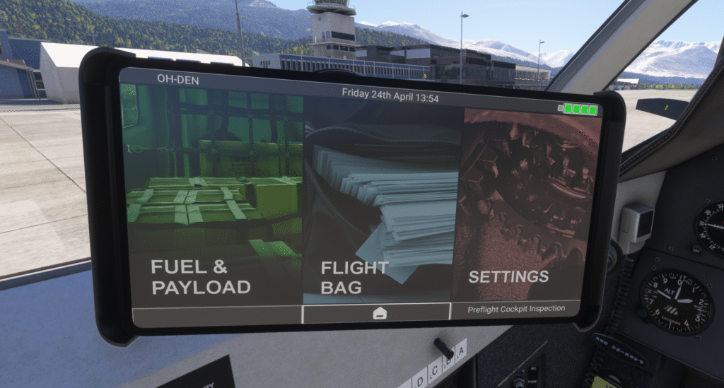
2.4 SWS Tablet #
The on-board tablet is on the pilot’s side and can be stowed and unstowed by clicking the shelf to the pilot’s left, under the circuit breaker panel. The tablet’s screen can be turned off by clicking the 3rd button, which will lock/unlock the tablet with every press.
Through the tablet you are able to:
- Load the aircraft with passengers and fuel (green section)
- Access the checklists and manual (blue section)
- Swap between GPS configurations, show/hide the passengers and crew, and change NWS modes (red section)
2.5 Cabin Drawers #
Drawers can be dragged open by clicking on their faceplate and dragging UP to close or DOWN to open them. A left/right operation was not possible due to the perspective being different depending on the camera position.
2.6 Exits #
Exits in all SWS aircraft open and close in a two-step process. The first step is to unlock the exit using the handle. When the exit is unlocked, a clickspot will become available that will allow you to open and close the door.
- To open the passenger exit, click on the red handle to unlock it, then click on the middle of the door to open or close it.
- To open the cargo door, first click on the handle area at the centre of the door. To open or close it, click on the area under the cargo door window.
2.7 Control Curves #
The plane was developed to be flown with linear response curves. Setting the curves to anything else will adversely affect the aircraft’s response to control inputs.
2.8 Take-Off Trim #
The trim indicators can be found on the forward edge of the pedestal. There are three indicators for aileron, rudder and elevator trim. Green markings on the indicators denote the optimum trim for take-off.
Elevator Trim #
Knowing your CG from the Weight & Balance step is important in setting the take-off trim correctly. The aircraft is trimmed nose-down in order to avoid early rotation on take-off. Take-off trim range is from the green rectangle down to the green diamond. For CG positions greater than 39% MAC, trim should be set to the green diamond.
Rudder Trim #
Due to the PC-12’s very powerful engine, the aircraft displays a strong tendency to yaw to the left when applying power — especially during the take-off roll. Rudder trim should be set in the green zone for take-off.
- For left crosswind: add more right rudder trim
- For right crosswind: add more left rudder trim
Rudder Pedal Input #
The PC-12 requires right rudder input during the initial take-off roll. As the rudder becomes more effective, pedal input is reduced and towards the end of the take-off roll, left rudder input will be required.

2.9 Aileron-Rudder Interconnect #
The aileron and rudder controls are mechanically linked with an interconnect system, whereby when the yoke is turned, the rudder pedals also follow in the same direction and vice versa. The purpose of the system is to assist turn coordination and reduce adverse-yaw. The aileron-rudder relationship is 1:1 up to 25 kts. After that point, the ratio of the interconnect begins to reduce and is very subtle above 150 knots.
As it is not possible to feel the control forces on a desktop controller, you will need to cross-control with your desktop controls. As you apply aileron control in one direction, the aircraft’s pedals will follow in order to better coordinate the turn. If you want to stop it, you will need to apply opposite rudder pressure to keep the pedals centred.
2.10 Stall Protection #
The stick pusher protects the aircraft from going into a stall by pushing the yoke forward. Published stall speeds for the PC-12 are not the actual aerodynamic stall speeds, but the speeds at which the pusher activates. The actual stall speed can vary depending on parameters such as aircraft weight, airspeed and load factor.
Each flap setting has an angle of attack range used for pusher activation, which results in certain airspeeds. The speed range for Flaps 40 is 51 to 65 knots indicated, and what airspeed the pusher triggers at depends on the current engine torque setting. Running the engine at idle will trigger the pusher at 51 kts, while higher settings will make it trigger at up to 65 kts. Activation speeds will be even higher if the ice protection system is active, or the plane is flying at a higher load factor.
Activation speeds with flaps up are significantly higher and can go up to 93 knots indicated, showing how large the aircraft’s safety margins and performance envelope can be.
2.11 Yaw Damper #
The yaw damper will reduce unintended movement around the yaw axis of the aircraft by automatically adjusting the pedals and rudder trim. The yaw damper should be turned OFF until after take-off is complete. It should remain on during all phases of flight and turned off during final approach.
The reason the yaw damper is turned off for take-off and landing is that it will react to pilot input by applying opposite control, thereby enhancing adverse control effects and putting the aircraft out-of-trim — potentially resulting in loss of aircraft control.
2.12 Yaw from Torque #
The PC-12’s engine has a strong effect on aircraft yaw and will pull the aircraft’s nose strongly to the left, especially when the yaw damper is off. This effect is simulated in the SWS PC-12, so you must be mindful of it — power changes will cause the nose to drift, especially on approach when the yaw damper is turned off.
2.13 Approach and Landing #
Correct Flap Settings #
Flap selection is typically determined by the prevailing flight conditions and runway availability. In standard scenarios, most operators opt for flaps 40. Flaps 15 is employed during instrument approaches, in gusty conditions, or when requested by ATC for a condensed approach. Flaps 30 is typically reserved for windy days, provided that the runway length allows for its usage.
Crosswind is a very important factor in determining flap setting for approach. Refer to the maximum demonstrated crosswinds table to decide the correct flaps for your situation.
Enter the Approach Easily #
The PC-12 is built to make flying easier for the pilot. You can stay ahead of the aircraft easily by using some rules of thumb:
- When flying level and clean (flaps up, gear up), setting engine torque to 15 psi will yield approximately 150 knots.
- With flaps 15 and gear up, a torque setting of 20 psi will get you back up to 150 kts.
- In the 150 kts speed range, the nose-down effect from the landing gear drag will cancel out the ballooning effect of Flaps 15 deployment — lowering both at the same time will keep your nose pointed in the same place.
Approach Tips #
A successful approach is determined by doing no more than what is necessary to keep the plane where you want it. Know how to manage the aircraft’s energy and use trim and subtle control inputs to direct it.
Rudder trim should be set one line left of the green zone. Further adjustment might be needed for crosswind. Torque setting used on approach is 9–12 psi, most often between 9 and 10 psi.
For a 500 fpm descent rate, the following settings apply:
| Flap Setting (Degrees) | Torque | Airspeed (kts) | Max Demo. Crosswind |
|---|---|---|---|
| 15° | 9–10 psi | 110–120 | 25 kts |
| 30° | 9–10 psi | 95–105 | 20 kts |
| 40° | 9–10 psi | 80–90 | 15 kts* |
As the aircraft bleeds off speed and settles into the approach, trimming the nose up will reduce the need for aft yoke application. This will make landing much easier, but beware in poor visibility conditions: in the event of a go-around you will need to aggressively prevent the nose from climbing because of the uptrim and speed increase.
Flaring and Touchdown #
The PC-12 will approach the runway with a nose-down attitude and if you lose awareness of that fact it will be very easy to land nose-first. For this reason, flaring should begin earlier than usual as you have more of an angle to cover.
- When crossing the “fence”, start bringing back the power.
- When over the numbers you should be idle and 10 kts below your approach speed.
- At the touchdown point you should just hear the stall warning horn.
- Before applying beta or reverse, make sure that you have full lateral control of the aircraft.
- When applying reverse, be ready to counter the left pull.
- At 50 kts, exit reverse and apply brakes.
3. Aircraft Overview #
3.1 Aircraft Description #
The PC-12/47 is a large, single-engine turboprop aircraft capable of performing a wide range of missions. The plane is used in the roles of cargo transport, air ambulance, commuter transport, executive transport and ISR platform. It is powered by a 1,200 hp engine; coupled with its high-lift wing this gives it exceptional short-field performance, while its pressurised cabin allows it to fly at altitudes up to 30,000 ft at speeds up to 269 KTAS.
Operating Limitations #
| Maximum operating airspeed | Lower of 236 KIAS or M0.48 |
| Maximum take-off weight | 10,428 lbs / 4,740 kg |
| Maximum speed, flaps ≤15° | 165 KIAS |
| Maximum speed, flaps >15° | 130 KIAS |
| Maximum landing gear operating speed | 177 KIAS |
| Maximum landing gear extended speed | 236 KIAS |
| Max demo. crosswind — Flaps 0° | 30 kts |
| Max demo. crosswind — Flaps 15° | 25 kts |
| Max demo. crosswind — Flaps 30° | 20 kts |
| Max demo. crosswind — Flaps 40° | 15 kts (landing only) |
3.2 Engine #
The aircraft is powered by the PT6A-67B engine, rated at a maximum take-off power of 1,200 hp and maximum cruise/climb power of 1,000 hp at 1,700 rpm. A constant-speed, 105″ Hartzell propeller provides thrust. The SWS PC-12/47 provides two propeller options, each separately modelled:
- The 4-bladed HC-E4A-3D aluminium propeller
- The HC-E5A-3A 5-bladed composite propeller
| Max Reverse | Max Cruise/Climb | Take-Off (5 min limit) | Maximum | |
|---|---|---|---|---|
| Power (hp) | 900 | 1,000 | 1,200 | 1,200 |
| Torque (psi) | 34.25 | 36.95 | 44.34 | 61.00 ¹ |
| ITT (°C) | 760 | 760 | 800 | 1,000 ² |
| Np (RPM) | 1,650 | 1,700 ³ | 1,700 ³ | 1,870 ¹ |
| Ng (%) | — | 104 | 104 | 104 |
| Oil Pressure (psi) | 90–135 | 90–135 | 90–135 | 40–200 ¹ |
| Oil Temperature (°C) | 10–105 | 10–105 | 10–110 | –40 to 110 |
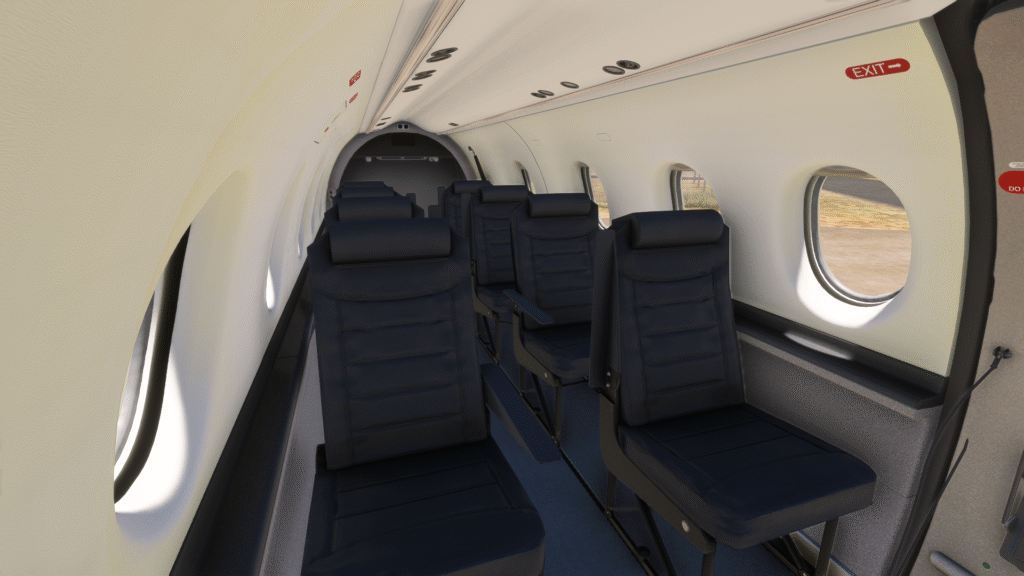
3.3 Interior Arrangement #
As of version 1.0, the SWS PC-12 comes with three interior arrangements: Cargo, Commuter and Executive. A medical interior is being researched for inclusion in a later version.
All cabins feature opening exits, visible payloads and custom animations where applicable.
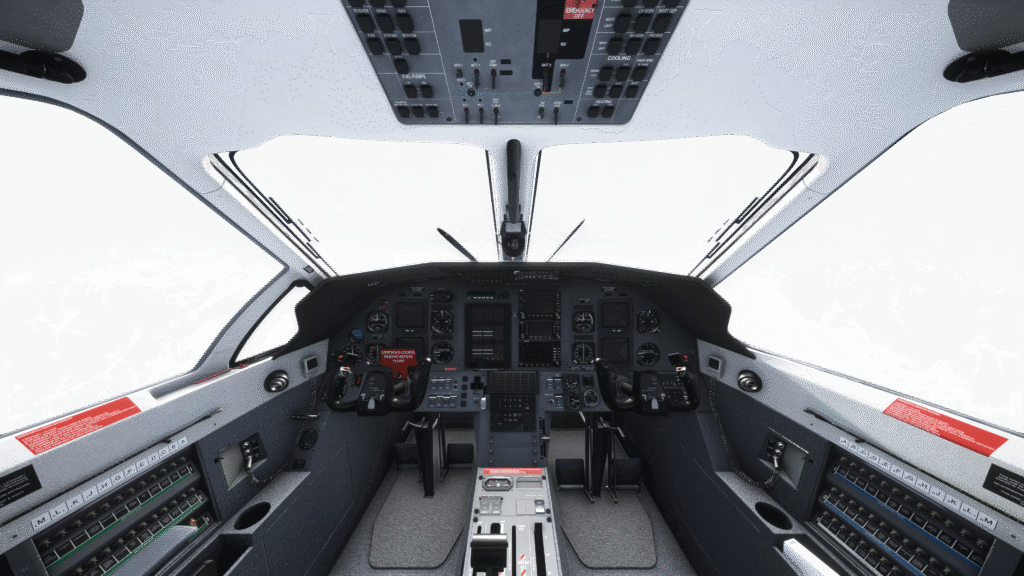
4. Cockpit Familiarisation #
The purpose of this section is to familiarise yourself with the cockpit layout and location of each instrument, while introducing the names and terminology for the systems that will be referenced in more detail later in this manual.
4.1 Pilot Panel #
- EADI
- Slip indicator
- EHSI
- RMI
- OBS
- Standby attitude indicator
- Airspeed indicator
- Flaps indicator
- Master caution light/pushbutton
- Master warning light/pushbutton
- KAS927B altitude selector
- TAWS control switches
- AM-250 altimeter
- Pilot AHRS selector
- Vertical speed indicator
The First Officer panel mirrors the pilot’s layout, except for the OBS (5) and standby attitude indicator (6).

4.2 Glareshield Panel #
- KMC321 Autopilot
- GMA340 Audio Panel

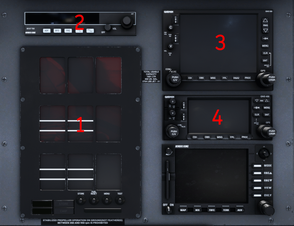
4.3 Centre Panel #
The centre panel contains the Engine Instrument System (1), ADF radio (2) and GPS units (3 & 4). The aircraft comes with the Working Title GNS530/430 by default. The first GPS unit (3) handles COM1 and NAV1 radios, while the second unit (4) handles COM2 and NAV2.
If you choose to install the GTN750 version, the layout will change to a GTN750 & GTN650 version of the cockpit. The GTN units may also include a built-in transponder.
4.4 Central Advisory Display Unit (CADU) #
The Central Advisory Display Unit (CADU) is located in the centre of the main panel, between the pilot and first officer knee panels. In the PC-12/47 it has an 8×6 layout, with three blank cells. Warnings are indicated in red, cautions in amber and advisories in green.
4.5 Pilot Knee Panel #
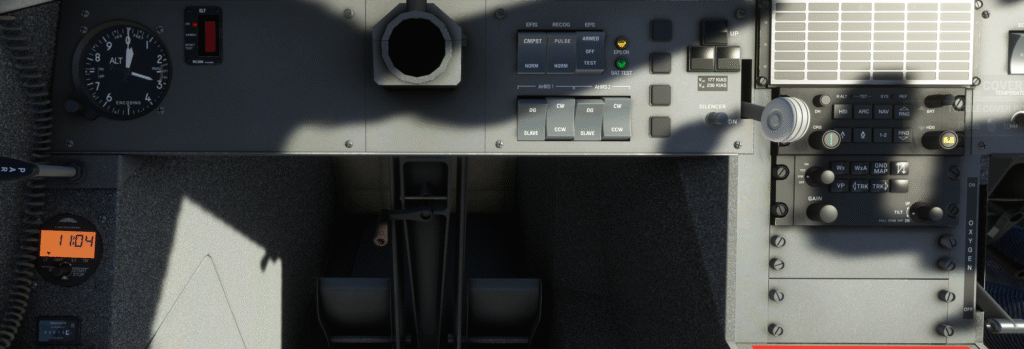
- Hobbs metre
- Thommen DC20 chronometer
- Standby altimeter
- Emergency Location Transmitter
- Yoke hider & gust lock
- Pilot EFIS Composite mode switch
- Pulse/steady switch for recognition lights and state indication
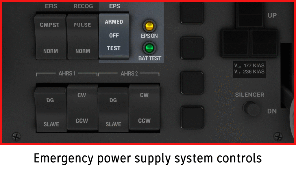
- Emergency Power Supply (EPS) switch and lights
- AHRS control panel
- Landing gear lights
- Landing gear lever
- EFIS50 CP467 control panel
- WXR RADAR control panel
- Oxygen lever
4.6 First Officer Knee Panel #
- Cabin Pressurisation Control System (CPCS)
- Yoke hider
- Transponder #2
- First Officer EFIS CP467 control panel
- First Officer EFIS Composite mode switch

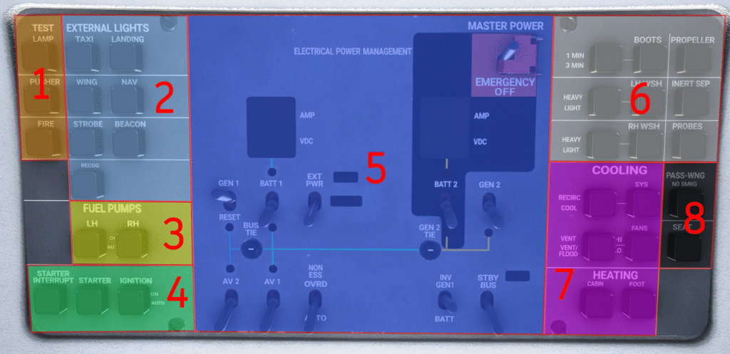
4.7 Overhead Panel #
The overhead panel is divided into eight areas:
- Test switches: LAMP TEST (illuminates all warning lights — on ground only for overhead/gear lights), PUSHER TEST (initiates the stick pusher test sequence), FIRE TEST (tests the fire warning system)
- External lighting switches
- Fuel pump switches: Two pushbuttons for the LH and RH fuel pumps — pushing toggles between AUTO and ON
- Starter/Ignition switches
- Electrical power management
- De-icing switches
- Air conditioning and heating switches
- Passenger warning switches
4.8 Pedestal #
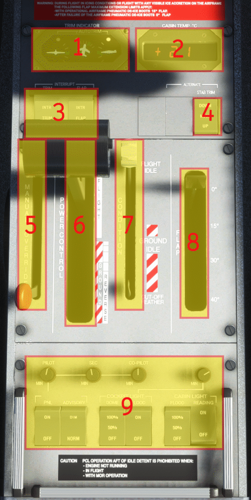
The pedestal is located between the two pilots’ seats and contains the following:
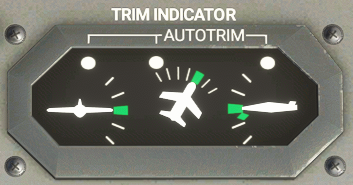
- Trim indicators: Three indicators for roll, yaw and pitch. Each has a green take-off trim range and an AUTOTRIM light that illuminates when the autopilot is using that trim.
- Cabin temperature indicator: Indicates current cabin temperature in degrees Celsius.
- Interrupt switches: TRIM INTERRUPT (de-energises trim circuits when set to INTR) and FLAP INTERRUPT (removes power from flap actuation; note — moving back to NORM will not re-energise the system until reset on the ground).
- Alternate Stab Trim: Normally used by the Autopilot; can be used as backup if the main trim actuator fails.
- Manual Override Lever (MOR): Used in the event of Fuel Control Unit failure to manually control fuel flow. While in use, the torque limiter is inactive — risk of engine over-stress exists. The PCL must be at IDLE before operating the MOR.
- Power Control Lever (PCL)
- Condition Lever: Three positions — CUTOFF (stops fuel flow and feathers propeller), GROUND IDLE (lower idle for ground operations), FLIGHT IDLE (minimum fuel flow for flight; ensures rapid engine response and full pressurisation system power).
- Flaps handle
- Interior lighting switches
4.9 Rear Pedestal #
The rear pedestal contains the levers for:
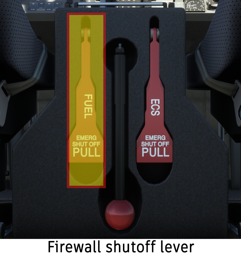
- Firewall fuel shutoff: Pulling the paddle lever cuts all fuel flow downstream of the firewall shutoff valve.
- Manual gear extension pump: Used in the event of a hydraulic failure; allows the pilots to manually lower the landing gear.
- ECS shutoff valve: Pulling the paddle lever cuts all power to the ECS and allows fresh air to enter the cabin via a fresh air duct on the bottom-right side of the nose. This allows the cabin to be cleared of smoke in the event of a fire.
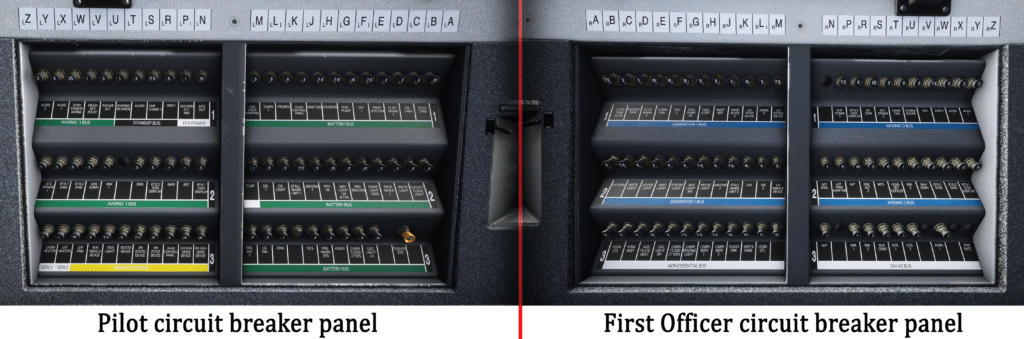
4.10 Circuit Breaker Panels #
There are two circuit breaker panels, one on each side of the cockpit. The circuit breakers allow the pilots to control power to each individual aircraft system. The circuit breakers will pop out automatically if excess current flows through the system.
5. Aircraft Systems #
5.1 Electrical System #
The SWS PC-12 electrical system consists of:
- Two 42 Ampere-hour batteries
- One 300A starter-generator
- A secondary 115A generator
- A 5 Ampere-hour Emergency Power Supply battery providing power to the standby attitude indicator and its light
- A ground power unit (INOP)
- Two inverters providing 26V 400Hz AC power to certain avionics components
The electrical system is controlled by the Electrical Power Management section of the overhead panel. Red light indicators in the overhead panel will illuminate when the respective bus is not powered.
Batteries #
Two 24V, 42Ah lead-acid batteries are installed in the aircraft’s tail compartment. Both batteries can provide power to start the engine. Battery 1 is connected to the BATTERY BUS BAR via the BUS TIE relay and also to the BATTERY DIRECT BUS BAR.
In the event of a double generator or engine failure, the batteries can supply essential electrical systems for 40 minutes if the load is reduced below 60A, or 60 minutes if the load is reduced below 50A.

Engine Generators #
The aircraft is equipped with two generators. A 28V DC, 300A Starter-Generator serves as the engine starter motor and is the aircraft’s main power source when energised. Generator 2 is a 28V DC, 115A generator which supplies essential services in the event Generator 1 fails. Generator 2 is not able to supply the full electrical system load.
Warning: When toggling the generators, Generator 1 should be turned on first and turned off second. If not done in the correct sequence, the high power demand will cause Generator 2 voltage to gradually decrease and the batteries will discharge.
Emergency Power Supply #
The Emergency Power Supply (EPS) system is connected to its own 5Ah battery. When active, the EPS provides power to the standby attitude indicator and its light. The EPS is controlled from the pilot’s knee panel through a three-position switch:
- OFF: EPS system is deactivated.
- ARMED: System is armed. When no generator and battery power is available, the EPS will activate and the amber light will illuminate.
- TEST: Tests the battery. If successful, the green BAT TEST light will illuminate after a few seconds.
Bus Bars #
The BATTERY BUS, GEN1 BUS and GEN2 BUS are connected to their respective power sources through the BAT relay, GEN1 relay and GEN2 relay, all controlled by switches in the overhead panel. Two indicators in the overhead panel show the Amperes and Voltage of each battery — negative Amperes indicate battery discharge, positive values indicate charging.
The AVIONICS 1 BUS is connected to the BATTERY BUS, and the AVIONICS 2 BUS is connected to the GEN1 BUS. The NON ESSENTIAL BUS is connected to the BATTERY BUS when GEN1 is on and the engine is running; an automatic load-shedding device will disconnect it in the event of an engine or GEN1 failure. The STANDBY BUS can be powered from AVIONICS BUS 1 (forward switch position) or directly from Battery 1 (ON position).
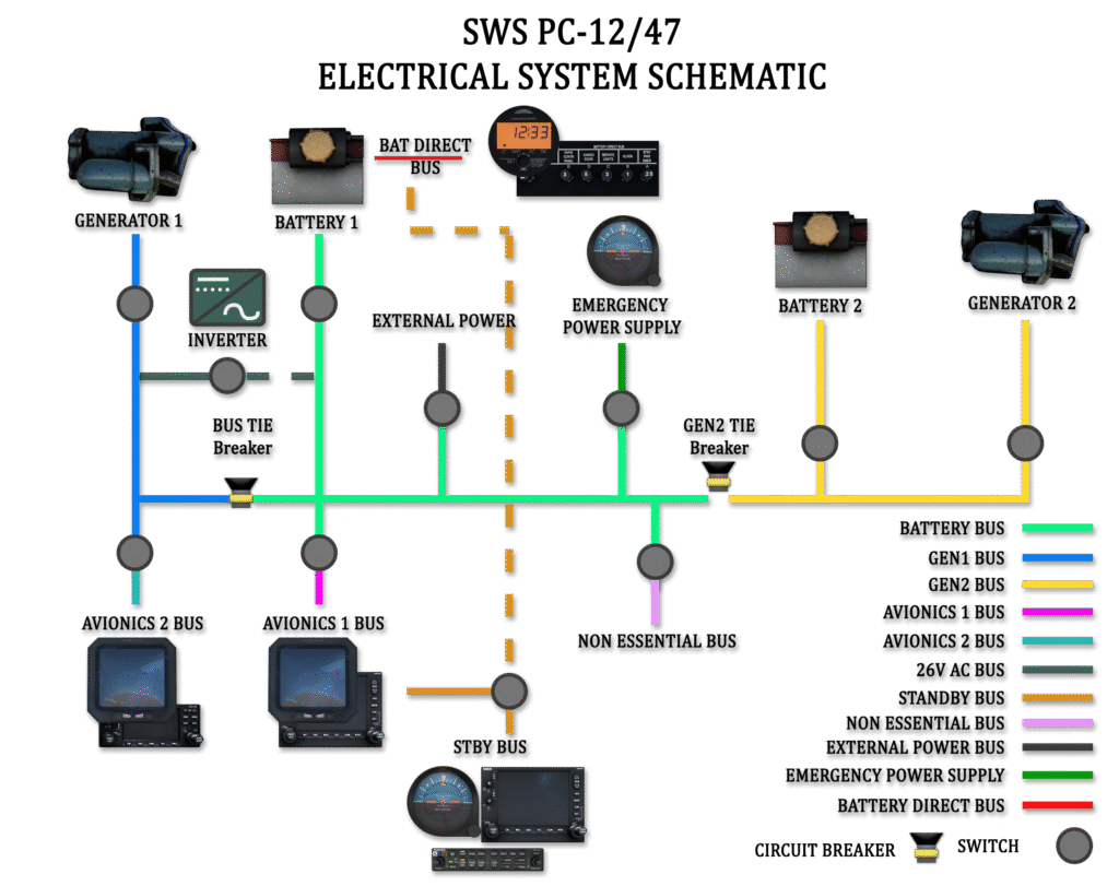
Bus Tie Interlock #
GEN1 is connected to the BATTERY BUS via the BUS TIE relay, and GEN2 is connected via the GEN2 TIE relay. The two relays have an automatic interlock. When both generators are on-line, the BUS TIE closes and GEN2 TIE is open. GEN1 supplies the GEN1 and BATTERY busses and charges Battery 1; GEN2 powers the GEN2 BUS and charges Battery 2.
When both generators are offline, both the BUS TIE and GEN2 TIE will close, allowing the batteries or external power unit to supply all bus bars. Both circuit breakers also serve as overcurrent protection devices: the BUS TIE opens automatically when continuous current exceeds 220A and the GEN2 TIE when current exceeds 145A.
Master Power Switch #
A master power switch protected by a red cover is located on the overhead panel. Moving the master power switch to the OFF position will remove all electrical power from the aircraft.
Circuit Breaker Panels #
The cockpit contains two circuit breaker panels, one on each side wall. Circuit breakers are labelled in columns from A to Z, with bus group labels below each row.
- Pilot side — forward panel: Systems powered from the BATTERY BUS bar.
- Pilot side — rear panel: Systems powered from GEN2, AVIONICS 1, STANDBY and EPS bus bars.
- First Officer side — forward panel: Systems powered from GEN1 and NON ESSENTIAL bus bars.
- First Officer side — rear panel: Systems powered from AVIONICS 2 and 26V AC bus bars.
EIS Indicators #
The EIS provides continuous monitoring of Generator 1 and Generator 2 voltages. In the event a generator is turned on but the output is zero, the EIS indications for that generator will flash to indicate a potential problem.
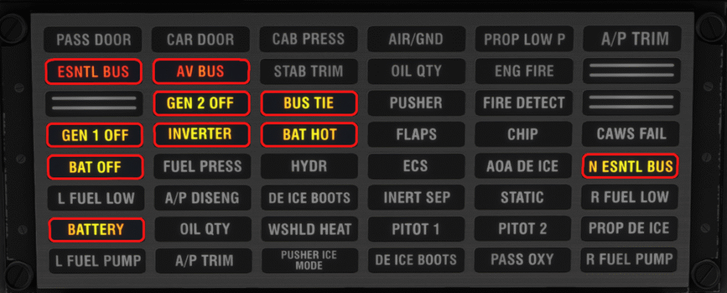
Electrical System CAWS Messages #
| Annunciator | Description | Voice Callout |
|---|---|---|
| ESNTL BUS | Voltage in GEN1, GEN2 or BATTERY BUS below 22V | Warning Essential Bus, Generator 1 / Generator 2 / Battery |
| AV BUS | Avionics bus voltage below 22V | Warning Avionic Bus |
| N ESNTL BUS | Non-essential bus voltage below 22V | — |
| BAT OFF | Battery is off-line | — |
| GEN 1 OFF | GEN1 is offline | — |
| GEN 2 OFF | GEN2 is offline | — |
| BATTERY | Battery current above 60A discharge or battery voltage above 29.6V (display will flash) | — |
| BUS TIE | BUS TIE open | — |
| INVERTER | Inverter output below 20V | — |
| BAT HOT | INOP on aircraft with lead-acid batteries | — |
5.2 Central Advisory and Warning System (CAWS) #
The Central Advisory and Warning System (CAWS) includes:
- The Central Advisory and Display Unit (CADU) panel
- An Aural Warning System
- A Caution pushbutton/annunciator on each pilot’s side
- A Warning pushbutton/annunciator on each pilot’s side
- The TEST LAMP pushbutton on the overhead panel
A Central Advisory Computer Unit (CACU) monitors aircraft systems and passes information to the CADU. Both systems are powered by 28VDC through the 5A CAWS 1 circuit breaker on the BATTERY BUS and the CAWS 2 circuit breaker on the GEN1 BUS.
CADU #
RED annunciations will make the WARNING pushbuttons illuminate. AMBER annunciations will make the CAUTION pushbuttons illuminate. Pushing either pushbutton will extinguish its annunciation, but the CADU indication will remain on for as long as the situation persists.
Test Lamp Pushbutton #
The TEST LAMP pushbutton is located at the top left corner of the CAWS panel and is used to test the CAWS annunciators. Pressing it on the ground illuminates the CADU, WARNING and CAUTION lights, overhead lights, flap indicator warning light and gear lights. Pressing it in the air will only illuminate the CADU annunciators.
Voice Callouts #
When the aircraft is on the ground and not fully powered, voice callouts are disabled to reduce nuisance alerts. Aural warnings resume 60 seconds after the engine start cycle has reached 50% Ng. Voice callouts are included for all Warnings (red annunciations), flap asymmetry, flap overspeed, stall, gear-up approach to landing, decision height, engine warnings, EGPWS and TAWS.
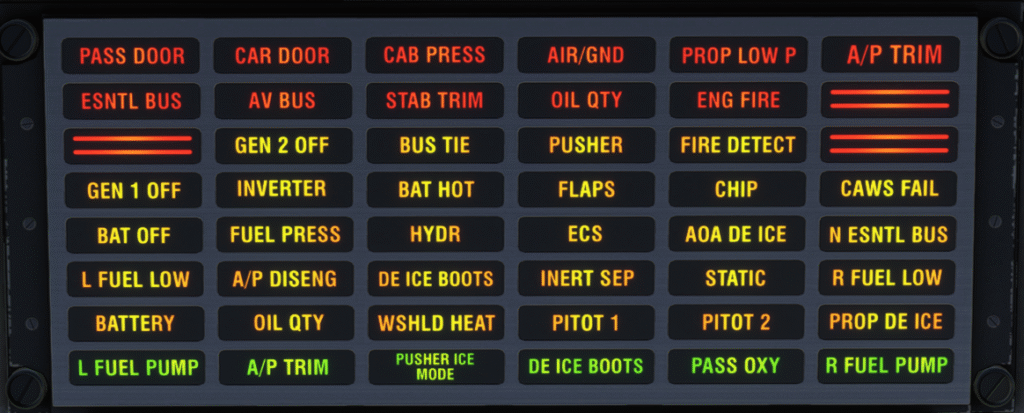
CAWS Annunciations — Full Reference #
| Annunciator | Description | Voice Callout |
|---|---|---|
| PASS DOOR | Passenger door and/or handle unlocked | Warning Passenger Door |
| CAR DOOR | Cargo door and/or handle unlocked | Warning Cargo Door |
| CAB PRESS | Cabin altitude above 10,700 ft or max cabin pressure differential exceeded | Warning Cabin Pressure |
| AIR/GND | Disparity between left and right AIR/GROUND switch | Warning Air Ground |
| PROP LOW P | Propeller pitch <6° while in-flight | Warning Prop Pitch |
| A/P TRIM | Autopilot and/or autotrim failure | Warning Autopilot Trim |
| ESNTL BUS | Battery, GEN1 or GEN2 bus voltage <22V DC | Warning Essential Bus Generator 1/2/Battery |
| AV BUS | Avionics bus voltage <22V DC | Warning Avionics Bus |
| STAB TRIM | Stabiliser trim unsafe for take-off | Warning Trim |
| OIL QTY | Low engine oil quantity (engine off) | Warning Oil |
| ENG FIRE | Engine over-temperature and/or possible fire | Fire Fire Fire |
| GEN 1 OFF | Generator 1 is off | — |
| GEN 2 OFF | Generator 2 is off | — |
| BATTERY | Battery over-voltage or over-current condition | — |
| BAT OFF | A battery is off | — |
| BAT HOT | INOP on aircraft with lead-acid batteries | — |
| BUS TIE | BUS TIE is open | — |
| INVERTER | Inverter output <20V AC | — |
| N ESNTL BUS | Non-essential bus voltage <22V DC | — |
| FIRE DETECT | Fire detection system malfunction | — |
| CHIP | Metal particles inside engine oil system | — |
| OIL QTY | Low engine quantity (engine running) | — |
| A/P DISENG | Autopilot pitch and aileron servos disengaged | — |
| A/P TRIM | Autopilot trim is operating | — |
| FLAPS | Flap system failure | — |
| ECS | Environmental Control System malfunction | — |
| HYDR | In flight: low hydraulic pressure. On ground: hydraulic pump cycled too often during flight (maintenance required) | — |
| FUEL PRESS | Fuel system pressure <2 psi (extinguishes above 3.5 psi) | — |
| L FUEL LOW | Left tank fuel quantity ≤20 US Gallons (75L) | — |
| R FUEL LOW | Right tank fuel quantity ≤20 US Gallons (75L) | — |
| L FUEL PUMP | Left fuel boost pump in operation | — |
| R FUEL PUMP | Right fuel boost pump in operation | — |
| PUSHER ICE MODE | Stick pusher computer operating in ice mode | — |
| PUSHER | Pusher system inoperative (malfunction, pilot decoupling, or self-test not completed) | — |
| CAWS FAIL | CAWS internal failure | — |
| DE ICE BOOTS | De-ice boots operating and pressure sequence correct (green) / De-ice boot system malfunction (amber) | — |
| WSHLD HEAT | Windshield heating system malfunction | — |
| PROP DE ICE | Prop de-ice system malfunction | — |
| INERT SEP | Inertial separator door operation failure | — |
| AOA DE ICE | AoA de-ice malfunction or DE ICING PROBES switch set to off (3-minute delay) | — |
| PITOT 1 | Pilot pitot head heater failure | — |
| PITOT 2 | Copilot pitot head heater failure | — |
| STATIC | Static port heater failure | — |
| PASS OXY | Adequate oxygen pressure to the passenger masks | — |
5.3 Fuel System #
Aircraft fuel is stored in two wing fuel tanks. Fuel is transferred through maintenance and firewall shutoff valves, a fuel filter, an air separator, a low-pressure engine-driven pump, a high-pressure engine-driven pump, and the fuel control unit.
The aircraft also contains two electrically driven boost pumps, one in each wing tank, used to balance fuel across the tanks or in the event of low fuel pressure. Fuel is loaded through one overwing fuel port on each wing. Each wing tank has a usable capacity of approximately 201 US Gallons (761L, 1,347 lbs).

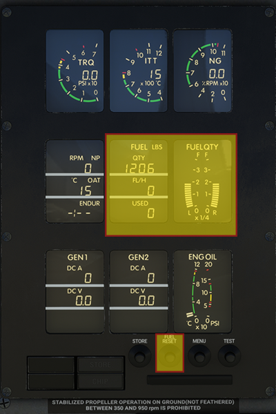
EIS Fuel Indications #
The EIS contains fuel quantity information as analogue and digital readouts. The FUEL QTY window indicates fuel quantity in real time on an analogue scale marked in quarters from empty to full. The FUEL window provides a digital readout of total fuel in pounds or kilograms.
Warning: Fuel quantity is the result of subtracting the engine fuel flow from the last FUEL RESET performed. If the aircraft has been refuelled, the indicated quantity will not correspond to the real fuel in the tanks, and the FUEL RESET button must be pressed. The FUEL RESET button is located at the bottom of the EIS.
Boost Pumps #
One electrically driven boost pump is located in each wing and is controlled by an overhead pushbutton that toggles the pump between AUTO and ON. When set to AUTO, the pump activates automatically when a fuel imbalance of more than 10.5 gallons is detected or when fuel pressure is low. Setting to ON forces the pump to operate continuously.
Firewall Shutoff Valve #
The Firewall Shutoff Valve prevents fuel flow to the engine during an emergency and can be closed by pulling the red paddle lever labelled “FUEL EMERG SHUT OFF” on the aft side of the pedestal.
5.4 Flight Controls #
The PC-12 uses a conventional set of flight controls using push-pull rods and carbon steel cables. An aileron-rudder interconnect system improves lateral stability and coordination during turn manoeuvres. The trim systems for ailerons, elevator and rudder are electrically powered and can be disconnected in a runaway condition. A trim indicator is located in the forward area of the pedestal.

Aileron-Rudder Interconnect #
The PC-12 aileron surfaces are linked using a spring package, forming an aileron-rudder interconnect (ARI) system to assist in coordinating turns and counter adverse yaw. Rudder pedal input will also move the aileron control system in the direction of turn.
| Airspeed (kts) | ARI Output on Rudder (max aileron input) |
|---|---|
| 25 | 100% |
| 50 | 63% |
| 100 | 43% |
| 150 | 30% |
| 200 | 21% |
| 230 | 17% |
Ailerons #
The ailerons are connected to the cockpit yokes by control cables in the fuselage and push-pull rods in the wings. The left aileron incorporates an electrically operated trim tab. The left aileron trim tab also acts, together with the geared tab on the right aileron, as balance tabs when the ailerons are moved.
Elevator #
The elevator is a two-piece unit attached to the horizontal stabiliser and connected to the cockpit control wheel by carbon steel control cables. Pitch trim is provided by an electrically controlled actuator connected to the movable horizontal stabiliser. A secondary trim motor controlled by the autopilot can also be used as a backup trim system.
The leading edge of the stabiliser moves down for nose trim up, and up for nose trim down. In the event of uncommanded trim operation, all trim operation can be stopped by pressing the TRIM INTR switch on the pedestal.
Rudder #
The rudder is a single piece unit attached to the vertical stabiliser and connected to the cockpit controls by carbon steel control cables. Both pilot and copilot pedals are adjustable by a crank between each set of rudder pedals. A rudder trim tab is electrically operated from the cockpit.
Flaps #
The PC-12 is equipped with electrically actuated Fowler-type flaps. Each wing has a single-piece flap, supported by three flap arms. Flaps may be set in one of four preset positions: 0°, 15°, 30°, 40°. A failure detection system monitors for flap failure or asymmetry — a CADU flaps caution will illuminate in such an event. In the event of flap overspeed, an “A/S” annunciator will illuminate on the flap position indicator.
Hint: Flap operation can be restored if the INTERRUPT FLAP switch is moved to NORM while parked and cold.
| Flap Setting | VFE (knots indicated) |
|---|---|
| 0° | Not applicable |
| 15° | 164 |
| 30° | 130 |
| 40° | 130 |
Trim #
A triple trim indicator is located at the forward end of the centre pedestal, containing indications for aileron, rudder and elevator trim. Take-off trim for each surface is denoted by green markings on the indicator. Each indicator is equipped with an AUTOTRIM annunciator that illuminates when the trim is operated by the autopilot, along with the green A/P TRIM advisory on the CAWS panel.
When the AIR/GROUND switch is in the ground position, a 60-second timer initiates. Upon expiry, the red STAB TRIM warning will illuminate on the CADU accompanied by a “Warning Trim” callout if stabiliser trim is not in the take-off position. The warning can be extinguished by trimming the elevator within the take-off trim limits.
5.5 Landing Gear #
The landing gear is a conventional tricycle configuration that is extended and retracted using hydraulic pressure produced by an electrically powered hydraulic pump. Landing gear extension and retraction is the only function of the hydraulic system and is completely automatic upon pilot selection. The gear lever is located on the right side of the pilot’s knee panel and is locked to the down position when on the ground.

Position Indicators #
Three indicator lights (green/red) and an aural tone with a silencer button indicate gear position. Green lights illuminate when the landing gear is down and locked. Red warning lights illuminate when the gear is in transit, not fully retracted, not down and locked, or when the gear is up with flaps extended beyond 15°. When the gear is fully retracted, all indicator lights are extinguished.
Nose Wheel Steering #
Nose wheel steering is achieved mechanically using the rudder pedals and differential braking. Using the rudder pedals allows the nose gear to turn ±12 degrees from centre, while differential braking allows deflection up to ±60 degrees from centre.
5.6 Cabin Pressurisation Control System #
The Cabin Pressurisation Control System (CPCS) controls the cabin by regulating the rate of exhaust of the outflow air that is provided for pressurisation and ventilation. CPCS operation is entirely pneumatic except when switching between ground and flight operating modes and during manual flight depressurisation.
The CPCS will maintain the selected cabin altitude up to a maximum pressure differential of 5.75 psi, equivalent to a 10,000 ft cabin altitude at 30,000 ft cruising altitude.

CPCS Control Panel #
The CPCS control panel is located on the first officer’s knee panel.
- ECS switch (top left): OFF removes power from the CPCS; AUTO provides electrical power for automatic operation; MANUAL allows the pilot to control the cabin pressurisation rate using the solenoid valve controller (top right).
- Cabin altitude selector (bottom right): In AUTO mode, sets the target cabin altitude via a rotary knob. Outer scale = cabin altitude; inner scale = cruise altitude.
- Rate of climb knob (bottom left): Adjustable from 100 fpm (10 o’clock) to 2,000 fpm (5 o’clock). The 12 o’clock position = 500 fpm.
- Dual cabin altitude/pressure differential indicator (centre top): Outer scale = cabin altitude in 1,000s of feet; inner scale = pressure differential in psi.
- Cabin rate of climb indicator (centre bottom): Indicates cabin rate of climb in thousands of feet per minute.
- CABIN PRESS guarded switch: Allows the pilot to manually depressurise the cabin. Alternate method: use the Bleed Air Firewall Shutoff valve at the aft end of the pedestal.

CPCS Auto Mode #
Before take-off, set the cruise altitude plus 500 ft into the cabin altitude selector and the pressurisation rate using the rate knob. Upon aircraft lift-off, the CPCS will begin pressurising the cabin at the commanded rate. At the top of descent, set the CPCS to the airfield elevation plus 500 ft.
If the cabin altitude exceeds 10,500 ±200 ft, or the cabin pressure differential is greater than 6.5 psid, the CAB PRESS warning will illuminate on the CADU, followed by the “Warning Cabin Pressure” voice callout.
CPCS Manual Mode #
CPCS manual mode is engaged by setting the ECS switch to MAN and using the MANUAL control knob at the top right corner of the panel. Rotating the knob clockwise increases outflow air, thereby increasing cabin altitude. Exercise caution to avoid rapid changes to cabin pressure.
5.7 Stall Protection System #
The PC-12 utilises a stick shaker/pusher system that prevents the aircraft from inadvertently entering a stall condition at low speed. When the aircraft is off the ground, two stall warning computers will individually provide a stall warning tone and stick shaker when the aircraft approaches the stall angle of attack.
The stall protection system calculates stall speeds using: stall warning computers, angle of attack, weight on wheels, de-icing system status, flap position, Power Control Lever position, engine torque, and self-test data. Stall speeds will vary with load factor, flap setting and PCL position.
Stick Pusher #
The stick pusher protects the aircraft from aerodynamic stall by pushing the nose down to reduce angle of attack, and is designed to engage approximately 5 kts above the aerodynamic stall speed. Both stall warning computers must be operating and the preflight pusher test must be completed for the system to be armed.
When operating in PUSHER ICE MODE, the stall AoA is increased to compensate for reduced lift caused by icing conditions. ICE MODE is engaged when the propeller de-ice is turned on and the inertial separator is in the OPEN position.
Stick Pusher Test #
The stall warning test can be performed in the air or on the ground. When activated in the air, only the stick shaker is tested — the pusher test portion is not performed. For a ground test, the engine must be running and generators must be on. The procedure is as follows:
- Set flaps to 15°.
- Press the PUSHER TEST switch on the overhead control panel.
- Move the power control lever forward until the stick shaker engages, then move it back to idle.
- The stick shaker will activate for 2 seconds.
- A 1-second pause follows.
- The stick shaker and pusher will activate. PUSHER ICE MODE and PUSHER annunciations will illuminate on the CADU.
- Hold the PUSHER INTR switch on the yoke — the PUSHER annunciation will extinguish and you should be able to move the yoke freely.
- After approximately 5 seconds, the PUSHER annunciation will come on again. Release the PUSHER INTR switch.
- Release the overhead PUSHER TEST switch.
- Test complete. Repeat on the other pilot side.
The stick pusher will be inoperative if not tested after starting the aircraft. It is prohibited to take off without completing the pusher test successfully. Following a successful test, the stick pusher is inhibited for 5 seconds after take-off to avoid inadvertent activation.
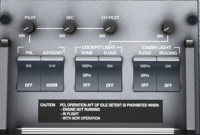
5.8 Internal Lighting #
Internal lighting controls are located on the back of the pedestal panel and allow control of the following lights:
- PNL: Turns on the instrument panel lighting. Three rheostats allow individual brightness control of the PILOT, SEC and CO-PILOT lighting.
- ADVISORY: When set to NORM, CADU warning/advisory lights are at maximum brightness. DIM illuminates them to 50% brightness — more suitable for night flying.
- DOME: Controls the cockpit dome lights. 50% turns on the left dome light; 100% turns on both.
- FLOOD: Controls the orange flood lights under the glareshield panel and over the circuit breaker panels. A rheostat controls brightness.
- Cabin FLOOD lights: Controls cabin flood lighting (OFF, 50%, 100%).
- Cabin READING lights: Turns cabin reading lights on or off. Individual dimmer switches are located at each seat where installed.
Two map lights are installed on flexible tubes over each circuit breaker panel. They can be repositioned by clicking and dragging, with scroll wheel to rotate the tip. Brightness is controlled by a rheostat at the light’s base; the MAP LIGHT switch on each pilot’s yoke turns them on and off.

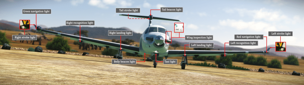
5.9 External Lighting #
External lighting is controlled from the external lights section of the overhead panel. The SWS PC-12 is equipped with the following lights:
- Navigation lights: One red light on the leading edge of the left wingtip and one green light on the right side of the WXR RADAR pod.
- Strobe lights: Three lights — one on each wingtip and one on the aft tip of the horizontal stabiliser fairing.
- Beacon lights: Two beacons — one at the belly of the aircraft (under the right wing root) and one at the top of the horizontal stabiliser fairing.
- Taxi light: One taxi light on the nose gear.
- Landing lights: Two lights, one on each main landing gear strut.
- Recognition lights: One recognition light under each wing, in the leading edge of the outboard fairing. Can operate in steady or pulse mode, selectable using the RECOG switch on the pilot’s knee panel.
6. Avionics #
6.1 Introduction #
This section will familiarise you with the avionics operation of the SWS PC-12 and their features. As the aircraft evolves, this section will be updated to include new functions added to the systems.
The following systems are covered: EFIS50, AM-250 altimeter, KMC321 Autopilot and KAS927B Altitude/Vertical Speed Preselector, Engine Instrument System, and the Thommen DC20 Chronograph.
The GNS530/430, GTN750/650 GPS units and GTX330 transponder are not covered by this manual.
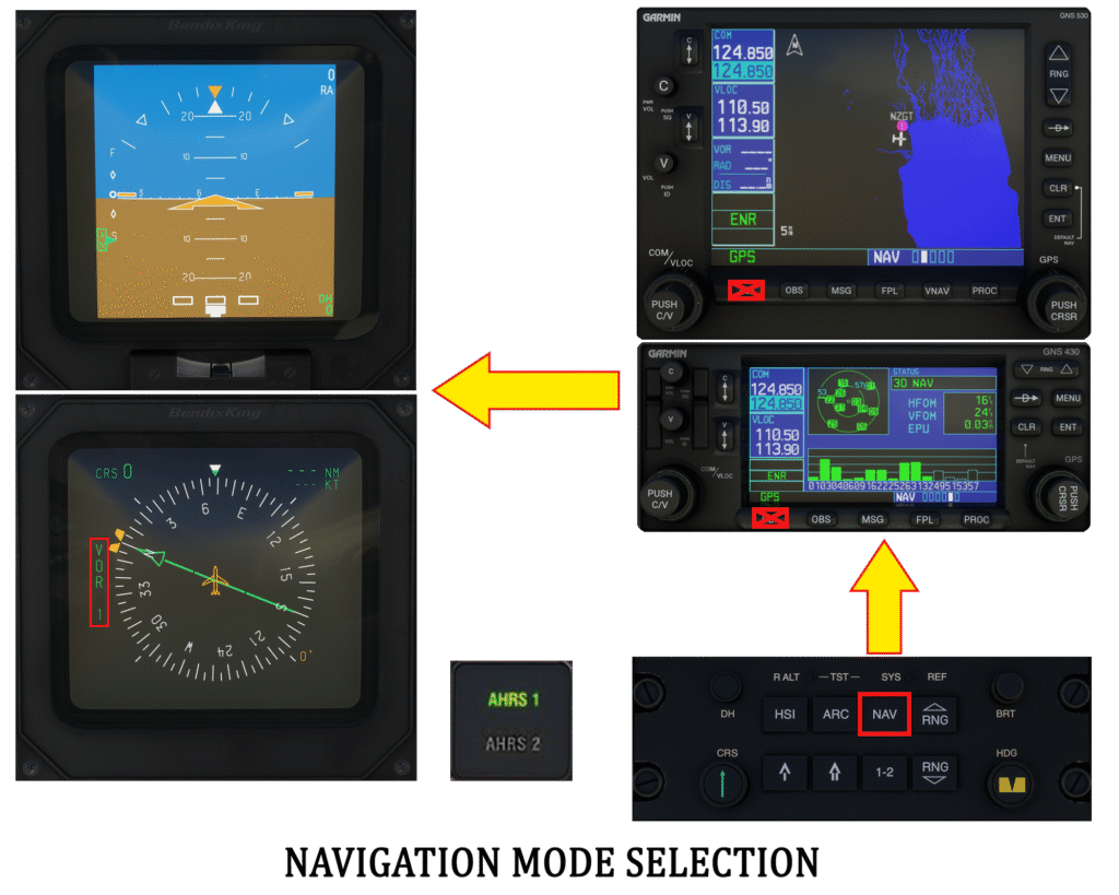
Navigation Systems Overview #
The SWS PC-12 navigation systems comprise two EFIS50 units (one per pilot), two Attitude-Heading Reference Systems (AHRS), two GPS units, and a KMC321 Autopilot with KAS927B Altitude Selector.
Each EFIS50 system is connected to an AHRS — the pilot EFIS to AHRS1, the first officer EFIS to AHRS2. Each crew member can change their AHRS source by pushing the AHRS pushbutton next to their EHSI. Navigation source is switched using the CP467 NAV button, selecting VOR/LOC, GPS or ADF. The pilot AHRS selection also determines which system feeds reference data to the autopilot.
Note: Switching navigation source using the CDI option on the GPS unit has been blocked as it is incorrect. The navigation source is tied to the AHRS, not the GPS units.
6.2 EFIS50 #
The EFIS50 system on the PC-12 comprises the following components:
- Electronic Attitude Direction Indicator (EADI)
- Electronic Horizontal Situation Indicator (EHSI)
- CP467 control panel
- Weather RADAR control panel (one unit only)

EADI Symbology #
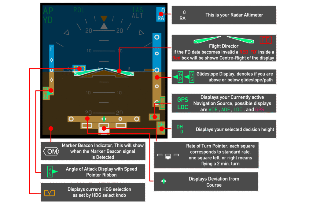
Two EADI screens are available, one on each pilot’s side. The ADI displays aircraft flight attitude from roll, pitch, yaw and heading data provided by the AHRS. Autopilot mode annunciations are shown at the top of the instrument. Angle of attack information is presented on the left side — “on speed” being 1.3 times the stall speed. An inclinometer at the bottom presents aircraft slip and skid.
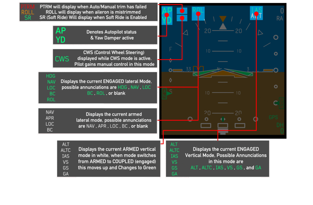
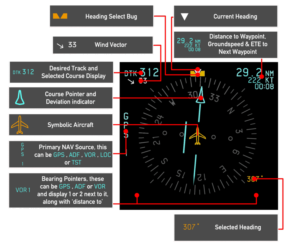
EHSI Symbology #
The EHSI operates in either a 360° compass mode or 120° arc mode. The display type is selected using the CP467 control panel. The EHSI shows current heading, desired track, bearing pointers, distance and groundspeed to the next waypoint, wind vector, and selected heading bug.
AHRS Control Panel #
The AHRS control panel is located on the right side of the pilot’s knee panel and controls the heading indicator mode.
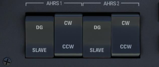
- SLAVE: Slaves the heading indicator to magnetic heading. Useful at lower latitudes where magnetic deviation is smaller.
- DG: Slaves the heading indicator to the directional gyroscope. In this mode the pilot can rotate the heading indicator clockwise (CW) or counter-clockwise (CCW) using the corresponding switch.
Some aircraft are equipped with a second AHRS, in which case two sets of switches will be available on the knee panel.
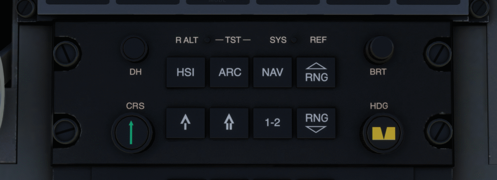
CP467 Control Panel #
There are two CP467 panels in the cockpit — one at the forward end of the centre pedestal for the pilot, and one for the first officer to the right of the yoke base. The CP467 controls EFIS functions and navigation source selection.
- DH knob: Sets the Decision Height (1 ft increments to 500 ft, 10 ft increments to 2,500 ft). An aural tone sounds when the aircraft descends below the set DH. Pull the knob to activate.
- Course knob (CRS, green arrow): Sets the OBS course for the selected navigation source. Pull to sync to current aircraft heading.
- HSI pushbutton: Cycles between HSI compass rose and HSI with NAV map.*
- ARC pushbutton: Cycles between ARC mode and ARC NAV map.*
- NAV pushbutton: Cycles the navigation source and EHSI between VOR/LOC, GPS and ADF modes.
- RNG up/down pushbuttons: Increases or decreases range while in NAV map mode.
- 1-2 pushbutton: Cycles between navigation source 1 and 2 (functional only in VOR/LOC mode due to MSFS limitations).
- Bearing pointer pushbuttons: Bearing pointer 1 (single-line arrow) and bearing pointer 2 (double-line arrow). Pushing cycles the pointer through VOR/LOC, GPS waypoint, ADF beacon, or off.
- Brightness knobs (top right): Bottom knob = EADI brightness; top knob = EHSI brightness.
- Heading select knob (HDG): Sets the autopilot heading. Pull to sync to current heading.
CP466 Weather RADAR Control Panel #
The CP466 panel controls the weather RADAR. The WX RADAR can be drawn in HSI and ARC mode, covering a 120° arc in front of the aircraft.
- Power knob: ON activates the WX RADAR and starts drawing on the EHSI.
- Wx: Draws precipitation using green, yellow, red and magenta colours (light to severe). WX is shown below the NAV source annunciator on the EHSI.
- WxA: The magenta area (severe precipitation) flashes between black and magenta.
- GND MAP (not simulated): Disables weather alerts and places the RADAR in ground mapping mode.
- LIGHTNING (not simulated): Enables lightning display when a weather mode is selected.
- VP (not simulated): Displays a vertical slice of weather or terrain ahead of the aircraft.


6.3 Autopilot #
The PC-12 autopilot consists of the KMC321 Mode Controller on the top centre panel and the KAS927B altitude/vertical speed preselector. The autopilot has pitch, roll and yaw axis controls. An automatic electric pitch trim system provides pitch autotrim during autoflight. A rudder trim relief function provides directional trim during yaw damper and autopilot operation.

KMC321 Mode Controller #

- HDG: Engages/disengages HEADING SELECT mode.
- NAV: Engages/disengages NAVIGATION mode. Tracks the selected EHSI primary navigation source. Glideslope coupling is inhibited in NAV mode.
- APR: Engages/disengages APPROACH mode. Captures and tracks the selected EHSI primary navigation source with approach accuracy. Glideslope coupling is allowed in APR Capture or Track mode. BC (Backcourse) is automatically engaged and disengaged.
- YD: Engages/disengages the Yaw Damper and rudder relief system. Can be toggled with the Autopilot disengaged.
- AP: Engages/disengages the Autopilot. YD and Flight Director modes engage automatically with AP on. YD remains engaged when AP is turned off.
- DN/UP: Controls the vertical axis. In IAS mode, adjusts the target airspeed; in VS mode, adjusts vertical speed in 100 fpm increments.
- ALT: Engages/disengages Altitude Hold mode at the current altitude.
- IAS: Engages/disengages Indicated Airspeed Hold mode at the airspeed at activation.
- FD: Engages the Flight Director in pitch Attitude Hold and Wings Level mode. Pressing FD when engaged disengages all FD modes if the autopilot is not engaged.
- SOFT RIDE: INOP due to MSFS limitations.
- HALF BANK: Reduces the maximum commanded bank angle to half for increased passenger comfort.
- TEST: INOP.
KAS927B Altitude/Vertical Speed Preselector #
The KAS927B is located at the top of the pilot’s panel. Two knobs allow preselection of a target altitude or vertical speed depending on the active mode.
In Altitude Preselect mode, the outer knob sets altitude in 1,000 ft increments and the inner knob in 100 ft increments. Pressing ALT ARM feeds the target altitude to the autopilot, which will enter altitude hold when that altitude is reached. Pressing VS ENG in this mode commands the autopilot to maintain the current vertical speed, rounded to the nearest 100 ft.
In Vertical Speed Preselect mode (pull the inner knob), the outer knob sets vertical speed in 1,000 fpm increments and the inner knob in 100 fpm increments. Pressing VS ENG feeds the selected vertical speed to the autopilot and arms the stored altitude. The KAS927 should be returned to Altitude Preselect mode once the desired vertical speed is set. If it remains in VS mode for 60 seconds or more, the screen will start blinking as a reminder.
- VS: Illuminates when Vertical Speed hold is engaged.
- ARM: Illuminates when ALT ARM is pressed and the autopilot is active.
- CAPT: Illuminates when the system switches from an active pitch mode to Altitude Capture mode, prior to engaging Altitude Hold.
- ALERT: Appears 1,000 ft prior to the selected altitude and extinguishes 200 ft before it. The ALERT light on the AM-250 and an aural tone also accompany this annunciation.
Note: The ENG and ARM buttons require the Autopilot to be on due to MSFS limitations.

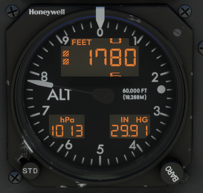
6.4 AM-250 Altimeter #
Two AM-250 altimeters are installed in the cockpit, one for each pilot. An analogue needle indicates barometric altitude in 100s of feet, while a digital readout indicates altitude from –3,000 to +60,000 ft in 10 ft increments on the upper half of the dial. When the aircraft is below 10,000 ft, two boxes appear on the left side of the display as a reminder.
Two screens at the bottom of the dial show the currently selected barometric pressure in hPa and inches of Mercury. An ALERT light at the 3 o’clock position is synchronised with the ALERT annunciation on the KAS927B. The Kohlsman knob at the bottom right sets the reference barometric pressure. The STD pushbutton at the bottom left resets the reference pressure to 1013 hPa / 29.92 inHg.
An altimeter reference bug can be moved around the perimeter of the dial by scrolling over the glass on the instrument.
6.5 DC20 Chronograph #
The DC20 Chronograph is situated on the left side of the pilot’s knee panel. It provides four functions:
- Local Time (LT): 12 or 24-hour format. Can differ from GMT only by hours.
- Greenwich Mean Time (GMT): 24-hour format.
- Elapsed Time (ET): Starts in min:sec, then hours:min, up to 99:59h.
- Timer (TR): Settable up to 59 minutes and 59 seconds; counts down to zero, then counts up.
The clock accuracy is within ±1 second/day, which is simulated in the SWS PC-12. The chronometer is operated through the knob under the display — rotating the knob switches modes; pressing performs mode-specific functions.
| Function | Press | Press (held) | Left rotation | Right rotation |
|---|---|---|---|---|
| LT | Set time | Change 12/24h format (10 sec. press) | Change mode / Set hour (in set time mode) | Nothing |
| GMT | Set time / Enter Test (10 sec. press) | — | Change mode / Set hour (in set time mode) | Change mode / Set minute (in set time mode) |
| ET | Start / Stop | Reset (>1 sec. when stopped) | Change mode | Change mode |
| TR | Set time / Enter / Start / Stop and set time / Enter | Reset (>1 sec. when entered) | Change mode / Set minute (in set time mode) | Change mode / Set second (in set time mode) |
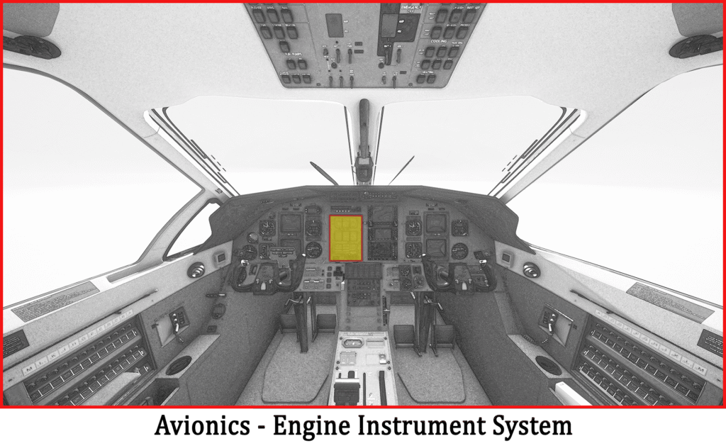
6.6 Engine Instrument System #
The Engine Instrument System (EIS) is situated in the middle of the cockpit panel. It is a computer-controlled system displaying engine and other system information, powered by the battery and GEN1 busses through the EIS1 and EIS2 circuit breakers.
EIS Screen Indications #
The EIS screen is organised in a 3×3 layout:
- Row 1 (engine parameters): Torque (0–70 psi)*, ITT (400–1,200°C)*, Ng (0–110%)*
- Row 2: Np and OAT/ITT and Endurance/Torque (MENU toggles between OAT/ITT and Endurance/Torque) | Fuel quantity, fuel flow, fuel used | Left and right tank fuel quantities
- Row 3: Generator 1 amperage & voltage | Generator 2 amperage & voltage | Engine oil temperature (0–120°C) and oil pressure (0–200 psi)*
EIS indications will blink at 40 times per minute in a caution state and 80 times per minute when in the warning range. On indicators marked with an asterisk, normal operating ranges are indicated with green bands, caution ranges with yellow, and warning limits with red lines and diamonds.

EIS Buttons #
- STORE: Captures a 20-second recording of every parameter and stores it with date and time. The STORE annunciation illuminates to confirm correct operation.
- FUEL RESET: Recalculates available fuel and updates the fuel totaliser.
- MENU: Moves Torque and ITT indications to Row 2 — used in the event of a display light failure in flight.
- TEST: Runs the built-in test sequence of the EIS.
EIS Cautions and Warnings #
| Parameter | Caution (40 blinks/min) | Warning (80 blinks/min) |
|---|---|---|
| Torque | 44.4 to 61 psi | 44.4 to 61 psi (after 20 sec. delay) or above 61 psi |
| ITT | 800–870°C; 870–1,000°C (start only); below 350°C (when Np>1,000) | 800–870°C (after 20 sec. delay); 870–1,000°C (after 5 sec. delay); above 1,000°C |
| Ng | Below 60% (engine running) | Above 104% |
| Oil Temperature | –40 to 10°C (Notes 1 & 2); 105–110°C | Below –40°C (Note 2); 105–110°C (after 10 min. delay); above 110°C |
| Oil Pressure | 40–60 psi (Notes 1 & 2); 60–90 psi (after 5 sec.); 135–200 psi | Below 40 psi (Notes 1 & 2); 40–60 psi (after 20 sec.); 60–90 psi (after 20 sec.); 135–200 psi (after 20 sec.); above 200 psi |
| OAT | Below +4°C and probes de-ice switch off (Note 2) | None |
| Np | Below 1,640 (after 5 sec., Ng above 90%); 1,760 to 1,870 | Below 950 RPM (on ground, after 5 sec. unfeather delay, Notes 1 & 2); 1,760–1,870 RPM (after 20 sec.); above 1,870 RPM |
| DC Volt Gen1 | Below 22V (after 3 sec., Ng >50%, Note 2); above 31.5V | None |
| DC Volt Gen2 | Below 22V (after 3 sec., Ng >50%, Note 2); above 31.5V | None |
7. Appendix #
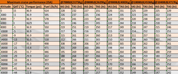
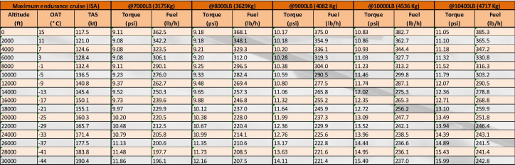
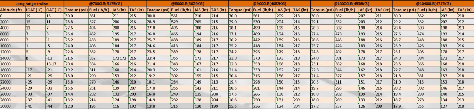
7.1 Cruise Performance #
Cruise performance tables (Maximum cruise performance ISA, Maximum endurance cruise ISA, and Long range cruise) are inserted manually below. Tables cover altitudes from 0 to 30,000 ft across gross weights of 7,000–10,400 lbs (3,175–4,717 kg) and list torque, fuel flow, IAS and TAS values.
7.2 Pusher Activation Speeds #
Speeds below are for level flight at 0° bank angle and 1G load factor. Increasing the bank angle and/or load factor will increase the angle of attack and therefore the pusher activation speed.
| Weight (lbs) | Flaps up (kts) | Flaps 15° (kts) | Flaps 30° (kts) | Flaps 40° (kts) |
|---|---|---|---|---|
| 6,400 | 72 | 59 | 53 | 51 |
| 7,000 | 76 | 62 | 55 | 53 |
| 8,000 | 81 | 66 | 59 | 57 |
| 9,000 | 86 | 70 | 63 | 61 |
| 10,000 | 91 | 73 | 67 | 64 |
| 10,428 | 93 | 76 | 69 | 66 |


