Introduction – What is CEX? #
CEX is short for Carriers Extended, a technology developed by SWS to bring unprecedented realism to FSX and Prepar3D’s naval aviation component.
Carriers Extended brings a vast array of capabilities such as simulated landing aids, custom animations, ship physics and AI aircraft, while maintaining an open architecture to allow third party ship developers to take advantage of the technology.
CEX features #
- Dynamic Deck Editor, allowing placement of static aircraft, crew & vehicles on the deck
- Animated arrestor cables
- Custom catapult system
- Deck state system that will automatically enable or disable catapults, lights or foul the deck depending on aircraft position and desired operational state
- Optical Landing Aids with realistic operation and stabilisation modes. FLOLS, IFLOLS, LRLS are currently supported, with more coming in!
- TACAN & ICLS (requires aircraft-side implementation)
- Independently controlled ship lights
- AI ship management system that controls the various ship lights depending on operational state, time of day and weather conditions
- Real-world weather-based ship physics
- SimObject attachment system to easily place landing aids and other objects on the ship without going into the modelling app (P3Dv4)
- PALS/ACLS interface for automatic carrier landings
- Custom SWS LSO and vLSO interoperability
- Shore-based FLOLS
- Fleet Placer utility, allowing the spawning of ship formations
- Drivable tow truck that can tow the user aircraft
- Support for multiple freeware and payware aircraft out of the box
Developement Process #
CEX folder structure #
Configuration files that control the various CEX features are located in %programdata%\SimWorks Studios\CarrierExtensions. In order for CEX to work properly, this folder should have full read/write permissions. A developer should cater for that during the installation process, whose requirements will be explained further down.
The CEX folders follow a very similar pattern to the FSX/P3D folder structure. Folders that are used to configure simobjects are separated by type (aircraft, ships, ground vehicles), while utility folders are separated based on their use. Below is the description of each folder and its contents.
ACLS #
ACLS stands for “Automatic Carrier Landing System”. Inside the ACLS folder a developer can place a configuration file containing data required for the aircraft to fly a hands-off approach onto the carrier. If a developer desires to implement CEX ACLS compatibility, please contact us via e-mail and we will assist you with the implementation.
Aircraft #
Contains aircraft configuration files. Similar in structure to the default sim’s files, it contains data for static and AI aircraft that will be populating CEX ships. For details about the content of the files, see CEX Aircraft Configuration File samples (download).
AirWings #
Contains air wing configuration files. An airwing consists of one or more squadrons that are assigned aircraft, to be used as statics and/or AI. This is defined in that wing’s configuration file.
Furthermore, the AirWings folder contains the logos of the squadrons which are displayed on the Dynamic Deck Editor. Logos can be 24-bit bmps, where pure black will render as transparent, or PNG/GIF with transparency.
For details about the content of the configuration files, download the CEX Air Wing Configuration File samples.
ConfigApp #
Contains art for the Dynamic Deck Editor, as well as aircraft icons and definitions used in it. Please do not modify the content of this folder. If you wish to include your own static aircraft definitions, please contact us through e-mail, sending us top-down images of the aircraft in PNG format with transparency, as well as the aircraft dimensions and we will update CEX.
GroundVehicles #
Contains ground vehicle configuration files. Developers should create their own subfolder in here to place their content. As an example, we use GroundVehicles\SWS_GroundVehicles, where all our vehicle-related art and configuration files are placed.
The folder has two uses:
- Tow tractor configuration files: these are used to create a driveable tow truck that can be called by the user to tow their aircraft.
- Vehicle fleets: Vehicle fleets are used to place stationary vehicles, crew and other non-aircraft objects on carriers.
- The modeller can create a scene with a forklift and a few people around it and export it as a simobject.
- It should be declare it in a vehicle fleet configuration file, so that it can be placed on a carrier’s deck.
- A top-down image in PNG form with transparency must be created and added to the folder, for use with the Dynamic Deck Editor.
Download the sample content for Vehicle Configuration Files here.
LSO Sound #
Contains audio files used by SWS’ LSO. Do not delete or modify the folder.
Ships #
This is the heart of the CEX system, as it contains ship configuration files for carriers and other surface vessels. Like with GroundVehicles, developers should create their own subfolder, containing the CEX Ship Configuration Files for their ships. Click here to download the sample file and documentation on Ship Configuration Files.
ShoreBased #
Contains configuration files for shore-based FLOLS installations. For placing shore-based FLOLS, please see the CEX Shore FLOLS Configuration File.
State #
Contains saved deck & animation states for CEX ships. You can create your own deck states in the simulator and give them to your customers as presets by copying the respective cfg files from this folder.
The CFG files are named with the UI Shortname declared in the ship configuration file, followed by _state.
Ensure that the files are NOT read-only before distributing.
SurfaceFormations #
Contains AI Carriers-style formation files that are seen by Fleet Placer and can be used to spawn formations of ships in the sim. Download the CEX Surface Formation Configuration File samples.
Ship modelling guidelines #
This section covers the process and caution points in the developement of CEX-specific features such as the animated arrestor cables. At your request via e-mail, we can provide access to source assets that you can use for your project and learn.
Variable naming #
All variables used for CEX animations need to follow the format ”’prefix_variablename”’. The prefix should be an identifier unique for the simobject you are creating. It can be anything you want, but should be at the start of every Lvar that you intend to use in a CEX-controlled animation.
Examples:
- SWS Midway uses the prefix cv_41. Example variable: cv41_wire1_pull
- SWS Coral Sea (both ’65 and ’73 versions) use the prefix cv_43. Example variable: cv43_park10
Reserved variables #
Ship system states
For the convenience and miscellaneous use of carrier and aircraft developers, the following general Lvars are created and updated by CEX when it is running. These are not prefixed by carrier.
| Variable name | Units | Description |
| CEX_Wire_Engaged | enum | Integer. If zero (0), then no wire is engaged by the tailhook. Numbers other than zero indicate the cable caught by the tailhook. Cables can be as many as needed. |
| CEX_Catapult_Engaged | enum | 1: catapult holdback engaged 2: catapult firing (0-100%) 0: all other times |
| CEX_in_groove | bool | 1: lined up on final and less than 1nm from the carrier. 0: not lined up on final or more than 1nm from the carrier. |
OLS and Cable variables
Two more sets of reserved variables pertain to the FSX-P3Dv3 FLOLS and cables. These are all using the prefix_varname format.In the table below, the prefix cv41_ is used.
For P3Dv4 an attachment system is used, which doesn’t require the lights to be built into the model. SWS has already created three ready-to-use landing aids which can be used by third-parties. These are provided as MDL files with all CEX products and can be assigned through the ship configuration file in the [OLS_X] section.
The simobject titles that can be used are:
- FLOLS
- IFLOLS
- LRLS
| FSX OLS variable name | Units | Description |
| cv41_ball_obstructed | bool | 1 if the ball is obstructed due to a foul deck. 0 if the ball is available to use. |
| cv41_BALL_VISIBLE | bool | 1 if the ball is on |
| cv41_Carrier_distance | number | Distance from the carrier, returned in Nautical Miles |
| cv41_GS_on | bool | 1 if the amber glideslope light is on. 0 if not |
| cv41_glideslope | number | Animation for the amber glideslope light. Range is 0-100 from bottom to top. |
| cv41_GS_red | bool | 1 if the red glideslope light (too low) is on, 0 if not |
| cv41_Ball_datum | bool | 1 if the inner datum lights are on, 0 if not. |
| cv41_Ball_datum_outer | bool | 1 if the inner datum lights are on, 0 if not. The outer datum lights remain on during a waveoff. |
| cv41_Cut_Lights | bool | 1 if the cut lights are on, 0 if not. |
| cv41_Ball_WO | bool | 1 if the waveoff lights are on, 0 if not. |
| Cable variable name | Units | Animation length | Description |
| cv41_wire1_pull | number | Can be defined in ship configuration file. It is recommended to use 1 keyframe per meter or better. | Denotes the longitudinal pull of the cable. 0 is the cable in its,neutral pose, with the last keyframe being the cable pulled at the tip of the landing area. “wire1” indicates the wire number. |
| cv41_wire1_side | number | Can be defined in ship configuration file. It is recommended to use 1 keyframe per meter or better. | Denotes the lateral pull of the cable. If a 0-100 range is used, 0 is the cable pulled fully left, 50 is centered and 100 is right. |
| cv41_wire1_height | number | Can be defined in ship configuration file. It is recommended to use 1 keyframe per meter or better. | Denotes the vertical pull of the cable (above the deck). If a range of 0-5 is used, 0 would be the cable at its neutral pose, while 5 would be the cable pulled up 5 metres over the deck |
Other ship animation variables
| Variable name | Units | Animation length | Description |
| cv41_cat1_shuttle_percent | number | 0-100 | Used for the catapult shuttles. “cat1” indicates catapult 1, “cat2” indicates catapult 2 and so on |
| cv41_cat1_JBD1_percent | number | 0-100 | Used for the jet blast deflectors of each catapult. JBD1 is the only available option currently. In the future, multible JBD entries will be made available, so that each JBD part is controlled independently |
| cv41_elev_1 | number | 0-1 | Controls the elevator’s position. 0 when the elevator is at the flight deck, 1 when at the hangar deck. Use a multiplier to match your keyframes. Elevator numbering begins at 1. |
| cv41_elev_1_flight_deck_rail | number | 0-1 | Controls the elevator’s safety rail at the flight deck level. When the elevator is about to move down, the railing comes up and remains until the elevator is on the flight deck again. Use a multiplier to match your keyframes. |
| cv41_elev_1_hangar_deck_rail | number | 0-1 | Controls the elevator’s safety rail at the hangar deck level. When the elevator is about to move up, the railing comes up and remains until the elevator is on the hangar deck again. Use a multiplier to match your keyframes. |
Lighting variables
Lighting uses simulation variables in order to be multiplayer compatible, but also to make the creation of multiple ships easier for the modeller, without having to create prefixed L:vars for every ship. This is especially important for those developers that want to quickly develop packages with tens of ships, while only using a single model for the each class.
For ship lighting to work, you must include the [LIGHTS] section in the sim.cfg file with all the relevant lighting entries, as described in the FSX and P3D SDK documents
| Light variable | Aircraft carriers | Helicopter-capable ships |
| (A:LIGHT RECOGNITION, bool) | Deck edge/Bow athwartship lights | LA lights/Obstruction lights |
| (A:LIGHT LANDING, bool) | Carrier: Landing area/CL/Dropline/Obstruction lights | Horizontal Reference Indicator lights |
| (A:LIGHT TAXI, bool) | Safe parking line | Safe parking line |
| (A:LIGHT STROBE, bool) | Orange deck floodlights | Orange deck floodlights |
| (A:LIGHT WING, bool) | White deck floodlights | White deck floodlights |
| (A:LIGHT PANEL, bool) | Bridge lights | Bridge lights |
| (A:LIGHT CABIN, bool) | Hangar lights | Hangar lights |
| (A:LIGHT LOGO, bool) | Island logo light (i.e. 68 on the Nimitz) | Logo light |
| (A:LIGHT NAV, bool) | Running lights | Running lights |
| (A:LIGHT BEACON, bool) | Other light | Other light |
Animated Arrestor Cables #
It is important to point out that default FSX/P3D arrestor cable attachpoints MUST BE REMOVED from the CEX-enabled carrier, otherwise the custom landing physics and animated cables will not work at all. If you wish to provide a non-CEX enabled version of the carrier, a separate model must be provided to your customers.
Modeling the cable
- Animated arrestor cables are created using skinned geometry and three animations per-cable to simulate their movement.
- When modeling the cable, be sure to make two cuts at the center of the cable. Where the cable meets the centerline of the runway, you should cut a section approximately 18cm (7 inches) in length, which is the part caught by the hook.
- When applying a material to the cable, make sure that the “Skinned mesh” box is checked. If using PBR materials, there is no such tickbox. PBR materials always behave as “Skinned”.
Rigging the cables
Our recommended rig has the following properties:
- All bones are merged into one object
- A skin modifier is applied
- An anchor bone is assigned to the cables’ tips, which will hold the edges of the cable in place
- A moving bone is placed on each cable’s center and weighs on the middle vertices. This bone is used to pull the cable when it moves
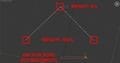
The images below illustrate the setup for the anchor bone, moving bone and skin settings used on our Midway class ships. The setup matches the samples available on our repository.

Animating the cables
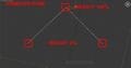
To animate the cable(s) you need to assign a skin modifier to each of the cables. For each cable, add the animated bone for that specific cable and the anchor bone (can be assigned to all cables). The following setup is used:
Keyframing the cables
- The animated bone will be at the center of each cable. This bone will be used to animate the cable for the three directions of motion and three animations will be applied to it.
- The middle bone will have a weight of 1.0 for the vertices of the middle section and 0.0 for the ones at the tips of the cable.
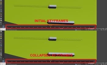
- The pull animations we use have 100 keyframes each. It is important that you collapse the animations to have one keyframe every frame, as that ensures maximum accuracy
- There are three animations that need to be applied to each bone. We recommend that you keyframe the neutral pose and Shift+Drag it along the timeline at every start, end and neutral keyframe. Then turn on autokey and animate the poses. This will ensure that all animations will look right.
- wireX_pull: Keyframes 0-100. 0 is the neutral position, 100 is the maximum pull along the centerline. A range of 0-100 is used for example purposes here. A larger value can be used, as stated in the OLS & Cable variables section.
- wireX_height: Keyframes 110-210. 110 is the neutral position, 210 is the maximum height it can be pulled above the neutral.
- wireX_side: Keyframes 240-340. At 240 move the bone to the left tip of the cable. At 340 move it to the right tip. 290 is neutral
IMPORTANT: When done animating, remember to collapse the animations (position collapse). Every frame should have a position keyframe to ensure maximum tracking accuracy of the cable.
- A second bone will be assigned to all the wires. That bone will have a weight of 100% at the tips of the cables and 0% at the middle section. This is an anchor that will keep the tips of the wires fixed to the spools.
NOTE: Certain developers don’t like applying more than one animation per-bone, as in the example above. This is understandable as the technique might be confusing. If you find it more convenient you can use three animated bones per cable. At models with many skinned animations, though, it may reduce the available bone count significantly.
Aircraft modelling guidelines #
This section covers the process and caution points in the developement of static and AI aircraft for CEX
Static Aircraft #
Static aircraft models must be modelled with their wings folded and their wheels being at a height of 0 (touching the grid). The aircraft must be deployed with a sim.cfg file, not aircraft.cfg!
A freeware aircraft package containing modern static aircraft will soon be available on our website. These static aircraft can be freely referenced with any freeware or payware carrier.
Tow truck modelling guidelines #
Truck models should ideally be less than 8000 triangles including the crew, to preserve performance at acceptable levels. LOD models for the truck are not necessary. To animate the trucks there are specific animations that are used for the moving parts.
Deployment #
In order to deploy a tow truck into the sim check the following list
- Tow trucks are deployed under SimObjects\Ground Vehicles
- They need an aircraft.cfg and airfile that will give them characteristics similar to a car. You can use our example files as-is or modify them.
- They need a panel.cfg to show up in MP. Ours are aliased to the Maule M260.
- For P3Dv4 an unrealistically very high mass is required in order to keep the vehicle stable. Ten times the real mass and MOI of the vehicle should do it.
If your truck is used in multiple carriers and you want to include unique “license plates”, you can add multiple fltsim.x entries in the truck’s aircraft.cfg and create differnt texture.x folders to accomodate the different textures, just like repainting a normal aircraft.
The smokesystem section is required to control visibility of towbars and random truck numbers. The template below is used for smoke entries that control visibility of parts. Indices up to 22 are used by our system, so if you desire to use a smoke effect in your trucks for exhaust effects, breathing or other puproses, start with (A:SMOKE ENABLE:23,bool) or higher. Add a “smoke.X=0.00, 0, -0.0, fx_dummy” line immediately after the reserved entries.
Towbar animation #
A vehicle may have:
- One towbar in the front
- One towbar in the back
- Two towbars, front and back
This is defined through the vehicle configuration files. The towbar moves in two directions:
- Left/right rotation: apply l_aileron_key to the towbar(s). It is important that the variable driving the animation is AILERON DEFLECTION.
- Keyframe 0 should be the towbar facing to the left (as seen from the driver’s perspective)
- Keyframe 100 should be the towbar facing to the right(as seen from the driver’s perspective)
- Up/down rotation: apply elevator_key to the towbar(s). It is important that the variable driving the animation is ELEVATOR DEFLECTION.
- Keyframe 0 should be the towbar leanind downwards
- Keyframe 0 should be the towbar leanind upwards
Each towbar needs to be linked to a polygon that will have a visibility tag applied to it, so they can be shown and hidden as needed.
- For the front towbar use: (A:SMOKE ENABLE:1, bool) !
- For the rear towbar use: (A:SMOKE ENABLE:1, bool)
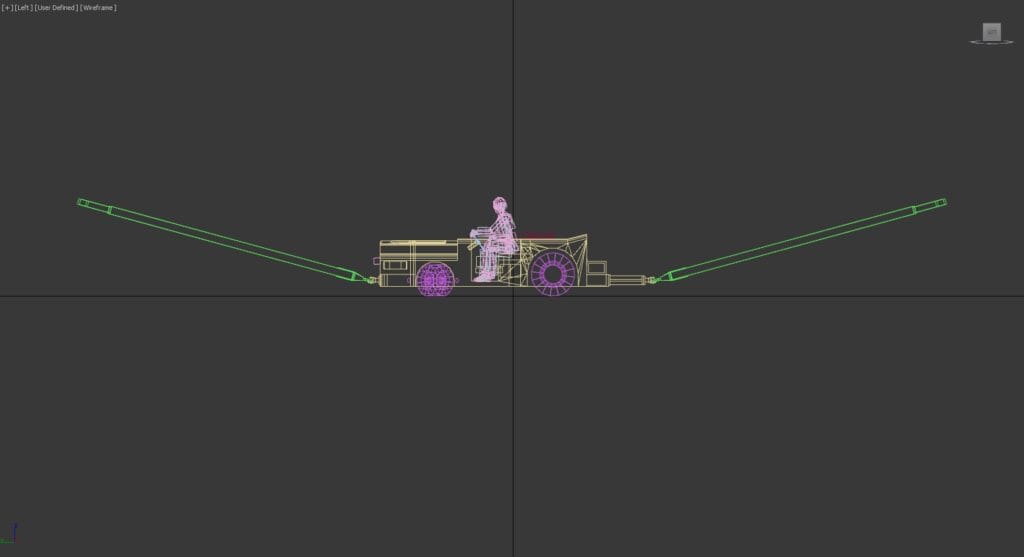
The images below illustrate the poses. Sample files can be found on our repository and accessed at your request.


Random truck numbers #
To have random truck numbers, you need to create a set of decals for the numbers from 0-99. Specifically:
- For numbers from 0-9 you need one polygon for each
- For numbers greater than 10 and up to 99 you need two polygons for each number. For example, #19 will need one polygon for the 1 and one for the 9. Both polygons will be visible, resulting in 19 to be seen on the vehicle.
- One polygon for each of tens, textured from 1-9
- One polygon for each of the units, textured from 0-9
- All polygons can be in the same decal sheet, as in the example model provided
To make them appear/disappear properly, we use the smoke system and visibility tags. Name them as follows:
- For the polygons pertaining to numbers 1-9 use the names tugid_s_001 to tugid_s_009
- For the numbers from 10-99 use:
- tugid_L_001 to tugid_L_009 for the 1x-9x (10s digit)
- tugid_R_000 to tugid_R_009 for the x0-x9 (1s digit)
Other animations #
The wheels animations used are:
- l_tire_still_key is used for the rotation of the left steerable wheel
- r_tire_still_key is used for the rotation of the right steerable wheel:
- c_tire_still_key is used for the rotation of the non-steerable wheels
- rudder_percent_key is used for the L/R steering animation, driver’s head and steering wheel.
Vehicle configuration files #
The vehicle & towbar’s geometric properties are defined in the vehicle configuration files. A sample file and explanatory document can be downloaded here.
Implementation of TACAN and ILS in flyable aircraft #
TACAN #
TACAN is supported on radio line of sight out to 150 nautical miles. It can be tuned through A:NAV ACTIVE FREQUENCY:1, A:NAV ACTIVE FREQUENCY:2, or through a dedicated L:var – (L:CEX_TACAN_Freq,MHz).
The set and read L:vars used by the aircraft’s tacan receiver system are shown below:
| Variable name | Read or Set | Description |
| (L:CEX_use_TACAN,bool) | Set | Set this to 1, otherwise CEX’s Navaids menu page will notify the user that TACAN is unusable due to lack of aircraft support |
| (L:CEX_TACAN_frequency,MHz) | Set | CEX TACAN will normally be tuned through the Sim’s native NAV1 and NAV2 frequency A:vars, however, it may also be tuned through this L:var |
| (L:CEX_nav1_has_TACAN,bool) | Read | Non-zero if the NAV1 active frequency A:var is tuned to a valid, in-range CEX TACAN |
| (L:CEX_nav1_TACAN_brg,degrees) | Read | TACAN radial. That is, the magnetic bearing from station to aircraft (using the magnetic variation at the station) |
| (L:CEX_nav1_TACAN_dist,nautical miles) | Read | Slant range from station to aircraft, in nautical miles |
| (L:CEX_nav1_TACAN_tx_lat, number) | Read | Latitude of tuned CEX NAV1 TACAN station |
| (L:CEX_nav1_TACAN_tx_lon, number) | Read | Longitude of tuned CEX NAV1 TACAN station |
| (L:CEX_nav2_has_TACAN,bool) | Read | Non-zero if the NAV2 active frequency A:var is tuned to a valid, in-range CEX TACAN |
| (L:CEX_nav2_TACAN_brg,degrees) | Read | TACAN radial. That is, the magnetic bearing from station to aircraft (using the magnetic variation at the station) |
| (L:CEX_nav2_TACAN_dist,nautical miles) | Read | Slant range from station to aircraft, in nautical miles |
| (L:CEX_nav2_TACAN_tx_lat, number) | Read | Latitude of tuned CEX NAV2 TACAN station |
| (L:CEX_nav2_TACAN_tx_lon, number) | Read | Longitude of tuned CEX NAV2 TACAN station |
| (L:CEX_lv_has_TACAN,bool) | Read | Non-zero if (L:CEX_TACAN_frequency,MHz) is tuned to a valid, in-range CEX TACAN |
| (L:CEX_lv_TACAN_brg,degrees) | Read | TACAN radial. That is, the magnetic bearing from station to aircraft (using the magnetic variation at the station) |
| (L:CEX_lv_TACAN_dist,nautical miles) | Read | Slant range from station to aircraft, in nautical miles |
| (L:CEX_lv_TACAN_tx_lat, number) | Read | Latitude of tuned CEX TACAN station |
| (L:CEX_lv_TACAN_tx_lon, number) | Read | Longitude of tuned CEX TACAN station |
| (L:CEX_TACAN_Freq, number) | Set | Frequency of CEX TACAN station in MHz |
| (L:CEX_TACAN_Chan, number) | Set | Channel of CEX TACAN station |
ICLS #
ICLS (carrier-based ILS) is supported in the form of a faithful implementation of the AN/SPN-41 equipment which has been standard on US carriers since the 1960s. The set and read L:vars used by the aircraft’s ICLS receiver system are shown below:
| Variable name | Read or Set | Description |
| (L:CEX_use_ICLS,bool) | Set | Set this to 1, otherwise CEX’s Navaids menu page will notify the user that ICLS is unusable due to lack of aircraft support |
| (L:CEX_ICLS_channel,enum) | Set | This variable should be set to a value between 1-20 inclusive, to tune the receiver |
| (L:CEX_ICLS_active,bool) | Read | Non-zero if the (L:CEX_ICLS_channel,enum) is tuned to a valid AN/SPN-41 which is in range and angular limits for reception. |
| (L:CEX_ICLS_lineup,degrees) | Read | Lineup error in degrees. If this is greater than zero, you are to the left of the centerline, if less than zero, you are right of the centerline. Used for your CDI animation. |
| (L:CEX_ICLS_glideslope,degrees) | Read | Glideslope error in degrees. If this is greater than zero, you are above the glideslope. If this is less than zero, you are below the glideslope. Used for the Glideslope needle animation. |
| (L:CEX_ICLS_basic_angle, number) | Read | Designated ICLS glidepath angle in degrees. This will be either 3.5, 3.75, or 4.0, depending on wind-over-deck or manually selected by the user, and applies to all visual and radio landing aids and LSO/vLSO on that ship |
| (L:CEX_ICLS_course, number) | Read | Current course along ship’s angled deck in degrees |
| Note: The glideslope angle can be changed by the user through the CEX options menu. | ||
PALS #
Carriers Extended currently supports a simulation of the AN/SPN-42 PALS (Precision Approach and Landing System). After the Datalink system is tuned to the AN/SPN-42, PALS will send error signals to the aircraft, which can be used by the Autopilot to guide the plane to an automatic landing.
Please bear in mind that CEX only provides the procedure and signals. Implementation of PALS into the aircraft’s autopilot controller will have to be done by the aircraft developer.
| Variable name | Read or Set | Description |
| (L:CEX_ACLS_channel, number) | Set | Datalink UHF frequency in MHz. If left 0, will automatically connect with closest transmitter |
| (L:CEX_ACLS_check_UTM,bool) | Set | If set non-zero and channel is valid, needles and waveoff variables will move according to the Universal Test Message pattern |
| Needles – approach angular errors according to PALS. Includes hook-to-eye, can be used for autoland | ||
| “(L:CEX_ACLS_lineup,number)” | Read | Angular error in degs left/right of landing area centerline |
| “(L:CEX_ACLS_glideslope,number) | Read | Angular error in degs above/below glideslope |
| Commands – PALS autoland pitch and roll commands calculated using the original SPN-42 algorithm evaluated using an ACLS cfg file with aircraft-specific parameters. Includes deck motion compensation (DMC) | ||
| (L:CEX_ACLS_pitch_command,number) | Read | Pitch command in degrees |
| (L:CEX_ACLS_roll_command, number) | Read | Bank command in degrees |
| Discretes – status messages from PALS system and/or operator, displayed in different ways on each aircraft | ||
| (L:CEX_ACLS_tilt, bool) | Read | No commands, needles, discretes being sent |
| (L:CEX_ACLS_voice, bool) | Read | System/operator requests downgrade to mode 3 approach |
| (L:CEX_ACLS_ack, bool) | Read | Operator requests an acknowledgment to test datalink. Acknowledge by resetting this value to zero |
| (L:CEX_ACLS_couple, bool) | Read | Operator is ready for pilot to couple autopilot to PALS |
| (L:CEX_ACLS_acl_rdy, bool) | Read | PALS radar is locked on – needles are valid |
| (L:CEX_ACLS_lnd_chk, bool) | Read | Datalink is ready, pilot should check gear/flaps/hook etc |
| (L:CEX_ACLS_cmd_ctl, bool) | Read | Pitch and bank commands are valid |
| (L:CEX_ACLS_ten_secs, bool) | Read | Deck Motion Compensation is being included in commands (not in needles). Actually 12.5 secs prior to touchdown |
| (L:CEX_ACLS_waveoff, bool) | Read | Operator/LSO waveoff (for foul-deck etc) or auto-waveoff due to error limits exceeded |


