Introduction #
Initially, F-4B aircraft weren’t equipped with any sort of EW equipment. During the mid-1960s, introduction of RADAR guided surface-to-air missiles in the Southeast Asia Theater led to the development, testing and introduction of various RADAR Homing and Warning (RHAW) and jamming systems, many of which were tested on the F-4 Phantom.
Our model simulates the AN/APR-25 RHAW system to the extent allowed by Tacpack. The F-4B/N also comes equipped with a noise jammer and countermeasure dispensers.
AN/APR-25 RHAW system #
The AN/APR-25 installation consists of:
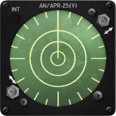
- the RHAW scope located in the forward and aft cockpit
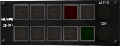
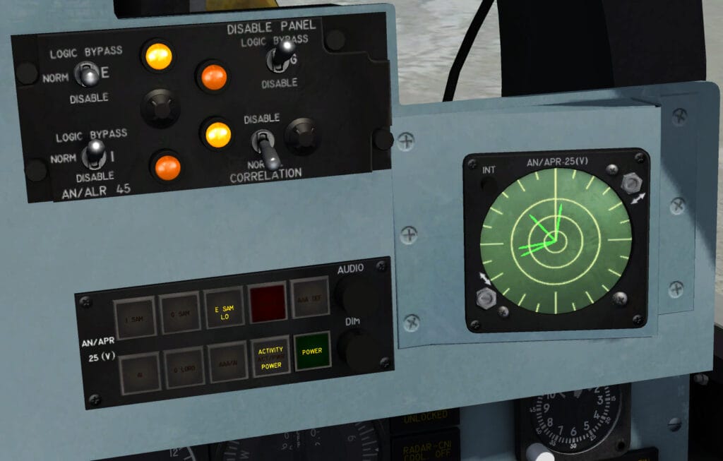
- the control panel and threat warning display located in the aft cockpit
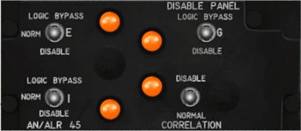
- the band disable panel located in the aft cockpit
- the threat warning lights located in the forward cockpit, mounted right, on the glareshield
- the volume control panel located in the forward cockpit, forward of the canopy jettison switch


Rear cockpit operation
To power up the AN/APR-25 set while in the aft cockpit:
- Click on the green button labeled POWER, located at the bottom right of the AN/APR-25 control panel and threat warning display.
- An amber POWER indication indicates that the system is active.
When a RADAR beam is pointed at your aircraft it is analyzed for azimuth, range and mode of operation. This information is relayed to the scope, threat warning lights and headphones. Threats are classified based on the frequency band they are emitting and their mode of operation.
A LOW light indicates that the threat is in search mode. A HI light indicates that the threat has acquired your aircraft and is in tracking mode. A HI light, accompanied with a flashing LAUNCH light will indicate that a launch is imminent or in progress and evasive manouevers must be taken.
The simulated lights and buttons are
- I band: SA-3
- E band: SA-2
- AAA combined with AAA AI light
- AAA AI: day fighter A/A RADAR
- AI: aircraft RADAR
- ACTIVITY: indicates that a RADAR beam is emitting towards the aircraft
- LAUNCH: indicates that a SAM launch is imminent
- AAA DEF: declutters the scope by removing AAA threats
When a RADAR beam is pointed at the aircraft, the AN/APR-25 will indicate it the following way:
- on the scope, a line will appear indicating azimuth to the RADAR station. The length of the line indicates the signal signal’s strength
- on the threat warning display the RADAR band and threat type lights will appear as listed above
- an audible tone indicates the source’s operating mode and band
When in a high clutter environment, the RIO is able to isolate specific bands that he considers important using the band disable panel. The panel allows the RIO to selectively disable the I, G or E band by moving the relevant switch from norm to any other setting.
The correlation switch works as a master switch which when set to DISABLE will deactivate all bands.
AN/ALE-29 countermeasures panel #
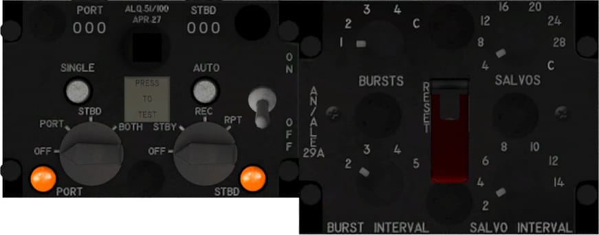
The AN/ALE-29 countermeasures panel is split in two parts, as displayed in the picture:
- Left: integrated control panel
- Right: programmer control panel
Integrated control panel #
At the top of the Integrated Control Panel (ICP) are two indicators showing total countermeasures loaded on each of the two containers, which are located on either side of the fuselage. Each container can carry a maximum of 30 cartridges of chaff and flares combined.
The AN/ALE-29 has no way of distinguishing what type of cartridge is loaded in each slot. The launched countermeasure will be the one loaded first.
NOTE: due to limitations countermeasure types are grouped together in the container. thus if a user loads alternating chaff and flares until the container is full the launcher will dispense 15 cartridges of chaff first loaded followed by 15 cartridges of flares. At this moment a mixed load of chaff-flare-chaff-flare etc cannot be dispensed in this “mixed” queue.
The SINGLE button is used to dispense a single countermeasure from each of the active containers (hotkey:X).
The AUTO button is used to deploy a salvo of countermeasures from the selected containers (hotkey:C) . The salvo settings are defined from the programmer panel which will be covered below.
The left knob controls the countermeasure doors.
- OFF closes both doors and stops any active dispensing program
- PORT opens the port countermeasure door and selects that container as the active one
- STBD opens the starboard countermeasure door and selects that container as the active one
- BOTH selects port and starboard countermeasure containers as the active ones, allowing concurrent dispensing from both
The right knob controls the noise jammer. OFF deactivates the noise jammer:
- STBY warms up the jammer. Warmup time is 30 seconds.
- REC stands for receive. The jammer will be passive, meaning it will receive RADAR signals but not repeat them towards the RADAR station.
- RPT stands for repeat. The jammer receives RADAR signals and repeats them. The enemy operator will then see a cloud of contacts in the direction of your aircraft thus being unable to distinguish fake signals from the real one until the aircraft is at a close range. The noise jammer is thus able to gain the F-4 a few precious extra seconds before SAM lock-on and the subsequent launch.
Programmer control panel #
The Programmer Control Panel (PCP) allows the RIO to set up a sequence of countermeasures to be launched using the AUTO button.
A sequence consists of a number of salvos which contain an amount of bursts. These are controlled through the knobs in the PCP.
The bursts knob controls how many bursts will be fired within a salvo. The settings are 1, 2, 3, 4 and C for continuous . The C option means that the countermeasures will keep firing until the selected container(s) is(are) expended or power is switched to OFF.
The burst interval knob sets the time interval between the firing of two cartridges, within a burst. Settings are 0.2, 0.3, 0.4 and 0.5 seconds
The salvos knob sets how many salvos will be fired. The options are 4, 8, 12, 16, 20, 24, 28, C. C stands for continuous and will keep firing salvos until the selected container(s) is(are) expended or power is switched to OFF.
The salvo interval switch controls the time interval between salvos measured in seconds. Options are 2, 4, 6, 8, 10, 12 and 14 seconds. An example of an AUTO sequence set from the PCP is given below:
- Bursts: 2
- Burst interval: 0.5
- Salvos: 4
- Salvo interval: 2
When the AUTO button is pressed:
- Salvo 1/4 starts
- Burst 1/2: a countermeasure is fired
- Wait for 0.5 seconds (0.5 second burst interval)
- Burst 2/2: a countermeasure is fired and salvo 1/4 is complete
- Wait for 2 seconds (2 second salvo interval)
- Salvo 2/4 starts and steps a, b, c begin again.
This process is repeated until 4 salvos are completed, countermeasures are expended or the power switch on the ICP is set to OFF.


