Disclaimer #
All information contained in this document is exclusively for use within Microsoft Flight Simulator. This document is not a manual for the real aircraft or any kind of training supplement and should not be used as such.
SimWorks Studios Ltd, Daher and Hartzell Propellers Inc. waive any responsibility for damages that may be caused by the use of this document in real aviation. For enquiries, contact SimWorks Studios Ltd. from 7:00–15:00 GMT at info@simworksstudios.com. For support, visit the SimWorks Studios knowledge base.
1. About the Aircraft #
The Kodiak 100 is high-wing, single-engine turboprop aircraft. It is capable
of transporting up to 9 passengers or cargo up to a distance of 1,132nm. The Series II aircraft was introduced in 2018, bringing the G1000 NXi, the ESI500 Electronic Standby Instrument and improved cabin sealing. Equipped with the Pratt & Whitney Canada PT6A-34 engine flat-rated at 750shp, the aircraft is capable of taking off and landing in less than 350ft, enabling it to
operate from small, unprepared airstrips all over the world.
With our rendition for Microsoft Flight Simulator we tried to capture every aspect of this magnificent aircraft. The current package features four exterior and five interior variations of the aircraft, created using factory CAD data and hundreds of images. Sound recordings were done in a real aircraft, capturing everything; the propeller roar, the engine whine, the door seals and switches, everything has been represented meticulously
Aircraft handling and performance were tested by pilots of the real aircraft and created using data from Daher and Hartzell. In the cockpit, most switches and circuit breakers are functional. The aircraft uses the default G1000 suite that comes with Microsoft Flight Simulator, but is also compatible* with the NXi mod. We have also developed a custom ESI500 standby instrument with full navigational capabilities.

2. Credits #
The Kodiak 100 was created under license by Daher Aerospace and made possible because of the hard work of the development team. The plane underwent many iterations and rebuilds to ensure that it holds up to the highest standards.
- Alessandro Schimicci, Kevin Miller, Alex Vletsas: 3D Modelling, animation
- Matt Wynn, Alex Vletsas: Exterior textures, seat textures
- Elias Strikos: Interior textures
- Paul Frimston: Flight dynamics
- Evripides Efthymiou: ESI500 and Air Conditioning screen
- Luca Pavan: G1000NXi plugins
- SimAcoustics: Aircraft and cockpit audio
- Maxim “Mugz” Brykov: Lighting effects
- Alex Vletsas: Systems, engine, programming, project coordination
We would also like to extend our thanks to Daher Aerospace, Kodiak Aircraft Inc and Aviation sans Frontières France who provided us with the resources required to make a high-quality rendition of the aircraft. Finally, we would like to thank our testing team for their patience and help during the long testing period, without which a lot of major issues would go unnoticed.
3. Settings #
We recommend the following settings:
- Crashes due to aircraft stress: Disabled. Flight Simulator may treat an exit opening in mid-air as overstress, which would prevent use of the storm window and skydive door.
- Flight model: Maximum realism, Modern Flight Model.
4. Product Overview #
4.1 Features #
The aircraft features fully animated control surfaces and cockpit, along withmany custom features that are listed below:
Flight Simulator 2020 #
- White paintjob plus 33 factory and 4 custom liveries
- Flexing landing gear
- Wheel chocks visible when the plane is cold
- Working exits and storm window
- Roll-up door and jump lights for the Skydive model
- Animated pilot and passenger armrests
- Animated air conditioning vents and cup holders
- Realistic backlighting and floodlighting
- Individually controlled reading and aisle lights
- Weight-based visibility of cargo and passengers in Tundra, Mixed and Cargo versions
- Rain and icing effects
- Custom air conditioning system with zone-based temperature behavior
- Custom G1000NXi EIS and checklists
- Custom ESI500 backup instrument
- Flap auto-trim system
- Custom fuel controller and ITT simulation
- Engine wear and tear: hot starts, cumulative damage from limit excursions
Flight Simulator 2024 additional features #
- 3D model refinements
- Modular aircraft built in accordance with the 2024-SDK
- Modelled cargo pod interior and engine bay
- Preflight features: pitot covers, chocks, engine oil, exits, cargo pod doors
- Integration with FS2024 tablet. Tablet can be stowed by clicking the pocket next to the pilot’s left leg.
- FS2024-native passengers and cargo in the cabin, different for each cabin configuration
- FS2024-native propeller animations
- Full G1000 NXi integration per the real aircraft manual and trainer
- ESI500 Synthetic Vision mode
- Dirt effects: mud, dust, bugs, runway dirt
- Career mode compatibility (FS2024 Marketplace and wheeled variants only)
- Smart engine autostart/autostop: when using CTRL+E, the system will intelligently control the start-up process to avoid damaging the engine
4.2 Selecting Aircraft Variations #
The SWS Kodiak comes with multiple exterior and interior configurations, that -depending on the simulator- can be selected in the Aircraft Selection screen or Presets. Available interior configurations are:
- Cargo: all-cargo interior
- Mixed/Combi: 4 passengers in front, cargo in the rear
- Timberline/Commuter: passenger version with 8 passenger seats
- Summit: executive interior
- Skydive: specially modified version for skydiving activities
Flight Simulator 2020 #
Exterior models can be found in the AIRCRAFT SELECTION section. Interiors are assigned per-livery and each livery is suffixed with the type of interior to indicate the cabin configuration:

Flight Simulator 2024 #
Aircraft configuration can be selected through the Variant tab in Aircraft Selection. Due to the large number of options available, we have elected to create colour-coded icons to facilitate the quick identification of variants without having to read the descriptions.


4.3 Payload #
Payload is controlled using the ingame weight menu and allows you to control visibility of the copilot, passengers and cargo. For the Tundra and Summit interiors, the seat that is located in front of the cargo door is hidden by default. To make it visible, add weight to Row 4 Left. The pilot, co-pilot and payloads can be shown or hidden by clicking on the fire extinguisher located at the pilot, co-pilot or cargo door
respectively.
Warning: Always load the aircraft within the Center of Gravity limits of 14–40% MAC. Exceeding CG limits can result in unexpected handling and loss of aircraft control.

Aircraft variations and payload
5. Aircraft Data Sheet #
| Empty weight | 3,775 lbs | Rotate | 60 KIAS | Cruise (max endurance) | 135 KIAS |
| Total fuel | 320 gal total, 315 usable | Takeoff | 79 KIAS | Cruise (max speed) | 174 KIAS |
| Max useful weight | 3,480 lbs | Takeoff climb (Flaps 20°) | 88 KIAS | Stall (full flaps / flaps up) | 47 / 61 KIAS |
| Maximum gross weight | 7,255 lbs | Enroute climb (Flaps 0°) | 101 KIAS | Barber pole | 182 KIAS |
The cargo pod variant weighs an additional 175 lbs.
| Flap position | Maximum speed (KIAS) |
|---|---|
| Flaps 10 | 138 |
| Flaps 20 | 120 |
| Flaps 35 | 108 |
| Max torque | 1790 ft-lbs @ 2200 rpm / 1970 ft-lbs @ 2000 rpm |
| Max climb torque | 1670 ft-lbs @ 2200 rpm / 1840 ft-lbs @ 2000 rpm |
| Propeller max RPM | 2,200 |
| Propeller caution range | 450–1050 |
| ITT normal range | 200–925°C startup / 400–760°C normal |
| ITT caution range | 925–1090°C startup / 760–790°C normal |
| ITT redline | 1090°C startup / 790°C normal (2 seconds max) |
| Oil temperature | Maximum 99°C; Normal 10–99°C; Caution -40–10°C; Minimum -40°C |
| Oil pressure | Maximum 105 psi; Normal 85–105 psi; Caution 40–85 psi; Minimum 40 psi |
6. Cockpit #
6.1 Forward Panel #
- Pilot Primary Flight Display
- Pilot Audio Panel
- Multi-function Display
- Copilot Audio Panel
- Copilot Primary Flight Display
- GMA700 autopilot
- Leveller switch
- TAWS inhibit switch
- ESI500 backup instrument
- Overspeed Governor test switch (INOP)
- Stall Warning test switch
- Left switch panel
- Right switch panel
- Pedestal
- Air conditioning panel
- Circuit breaker panel
- Coffee cup holder
- Door latch
- Tablet hide/unhide clickspot FS2024

Forward panel
6.2 Overhead Panel #
- Pilot shoulder harness lock lever
- Left fuel tank selector
- Right fuel tank selector
- Copilot shoulder harness lock lever
- Pilot reading light
- Pilot reading light switch
- Overhead light
- Overhead light switch
- Copilot reading light
- Copilot reading light switch

Overhead panel
6.3 Switch Panels #
The left and right switch panels are located at the lower end of the instrument panel, to the left and right of the parking brake lever. The left panel controls fuel pump, starter and electrical systems, while the right panel controls lighting and de-icing systems.

Switch panels overview
Left Switch Panel #
The Left and Right Switch Panel are located at the lower end of the instrument panel, left and right of the parking brake lever. The left switch panel contains the switches that control the aircraft’s fuel pump, starter and electrical system, while the right switch panel contains the lighting and de-icing system switches
- Battery Master Switch: The battery master switch is a red, two-position switch located on the lower left corner of the instrument panel and is labeled MASTER. When the switch is in theON position, battery power is supplied to the two main buses and the Essential Bus. The OFF position cuts off battery power to all buses.
- Avionics Master Switch: The avionics master switch is a white, two-position switch located on the lower left corner of the instrument panel adjacent to the Battery Master Switch and is labeled AVN BUS. When the MASTER and AVN BUS switches are placed in the ON position, battery power is supplied to the avionics bus.
- Auxiliary Bus Switch: The auxiliary bus switch is a white, two-position switch located on the lower left corner of the instrument panel adjacent to the Avionics Master Switch and is labeled AUX BUS. When the MASTER and AUX BUS switches are placed in the ON position, battery power is supplied to the auxiliary bus. The environmental control systems are powered by the auxiliary bus. The AUX BUS switch is provided for ease of load shedding should an electrical power failure occur.
- Fuel Pump Switch: The switch labeled AUX FUEL PUMP is a three-position switch located on the lower left corner of the instrument panel. The switch controls the operation of the aircraft’s Auxiliary Fuel Pump and has positions for OFF, STBY and ON. The Auxiliary Fuel Pump requires electrical power to be available in order to operate. When set to OFF, the fuel pump will be turned off. When set to STBY, the fuel pump will turn on when the fuel pressure drops below 4psi and automatically turn off if the engine can sustain a pressure of 4psi or higher. Putting the switch in the ON position will turn on the fuel pump.
- Ignition Switch: The ignition switch is a two-position toggle-type switch labeled IGNITION and is located on the lower left corner of the instrument panel. The switch has positions for OFF and ON.
- Starter Switch: The starter switch is a three-position toggle-type switch labeled STARTER and is located on the lower left corner of the instrument panel. The switch provides positions for OFF, LO/MOTOR, and HI START.
- Generator Switch: The generator switch is a two-position toggle-type switch labeled GENERATOR and is located on the lower left corner of the instrument panel. The switch has positions for OFF and ON. When the generator switch is placed in the ON position, the Master Control Unit will automatically control the generator line contactor for normal operation of the generator. When the switch is placed in the OFF position, the Master Control Unit will disconnect the generator from the electrical system.
- Alternator Switch: The alternator switch is a two-position toggle-type switch labeled ALTERNATOR and is located on the lower left corner of the instrument panel adjacent to the GENERATOR switch. The switch has positions for OFF and ON. When the alternator switch is placed in the ON position, the Alternator Control Unit will automatically control the line contactor for normal operation of the alternator, and the alternator will supply power to the Essential Bus. When the switch is placed in the OFF position, the Alternator Control Unit will disconnect the alternator from the Essential Bus.

Right Switch Panel #
- Beacon Light Switch: The switch controls an aviation red LED flashing beacon that is installed on the top of the fuselage near the vertical tail. The flashing beacon is utilized as an additional source for anti-collision protection in-flight and for recognition during ground operations. The flashing beacon is protected by a circuit breaker labeled NAV LIGHTS.
- Strobe Lights Switch: A high intensity LED strobe light system is installed on the airplane. The system includes two white strobe lights, one on each wing tip. The lights enhance the anti-collision protection for the airplane and meet the FAA requirements for night operations. The strobe lights are protected by a circuit breaker labeled STROBE.
- Navigation Lights Switch: LED navigation lights are installed on the wing tips and the tail-cone stinger. The navigation lights are protected by a circuit breaker labeled NAV LIGHTS.
- Taxi Lights Switch: Two incandescent taxi lights are installed on the airplane, one in each outboard wing leading edge. The lights are positioned to provide adequate lighting for taxi operations. The taxi lights are protected by a circuit breaker labeled TAXI LIGHTS.
- Landing Lights Switch: Two high intensity discharge (HID) xenon landing lights are installed on the airplane, one in each outboard wing leading edge. The lights provide illumination forward and downward for accomplishing night takeoffs and landings. The lights are protected by a circuit breaker labeled LANDING LIGHTS. The landing lights are also utilized as pulsing recognition lights. When the landing light switch is placed in the PULSE position, the landing lights initiate an alternating pulsing sequence, providing great visual recognition by other aircraft. Pulse Landing Lights will not begin their strobe operation until 30 seconds after the landing lights have been turned ON.
- Cabin Lights Switch: Cabin overhead lighting consists of four main cabin lights and two cockpit reading lights. The cabin overhead lights are controlled by a three-position switch (ON-NORM-OFF) labeled CABIN. When the CABIN light switch is placed in the NORM position, the optional cabin overhead reading lights may be turned ON at each individual reading light throughout the cabin.
- Instrument Panel Lighting Knobs: There are two super-positioned knobs that control instrument panel lighting, labeled INSTRUMENT PANEL. The outer knob controls the intensity of the rope-type LED light strip that is mounted under the glareshield. The inner knob controls the backlighting intensity of the G1000, audio panels and autopilot panel. The instrument panel lights are protected by the circuit breaker labeled PANEL LIGHTS.
- Switch Panel Lighting Knob: The knob labeled SWITCH/CB PANEL controls the backlighting of the switch panels and circuit breaker panel.
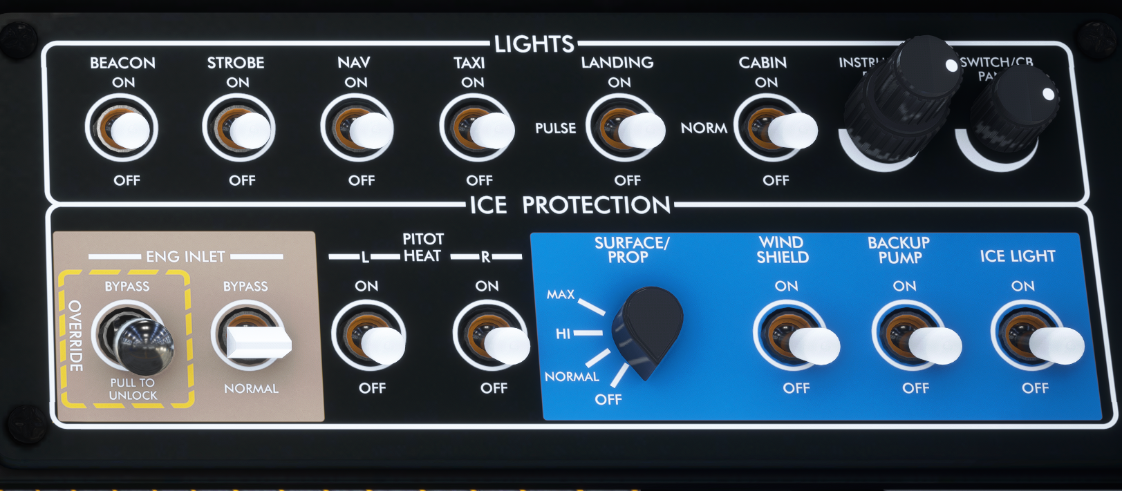
Right switch panel
6.4 Centre Panel and Pedestal #
- Hobbs metres
- Emergency Location Transmitter
- Oxygen panel
- Aileron trim switch
- Firewall fuel shutoff lever
- Elevator trim wheel
- Emergency power lever
- Power lever
- Propeller lever
- Conditioning lever
- Flap handle
- Rudder trim switch

Centre panel and pedestal
HOBBS METRES: #
Two Hobbs metres labeled FLIGHT TIME and BLOCK TIME are installed in the middle of the lower part of the instrument panel. The BLOCK TIME Hobbs metre records the hours of engine use. The FLIGHT TIME Hobbs metre records the hours of flight time and is activated by a squat switch.
EMERGENCY LOCATOR TRANSMITTER: #
The Emergency Locator Transmitter is located aft of the rear cabin bulkhead; it is controlled by the red-coloured switch located in the middle of the instrument panel, to the right of the Hobbs metres. The ELT switch has three positions: TEST, ARM OFF and ON.
OXYGEN PANEL: #
The SWS Kodiak includes a simulated oxygen supply, with varying depletion rate depending on the number of passengers on board. When a station carries a weight that is 120lbs or greater, the system considers that a passenger is present in that station. Oxygen quantity is indicated by the lights to the left of the oxygen switch. The light labeled O2 REQ illuminates if the oxygen pressure is at 400psi or less, indicating a low oxygen supply. The light labeled FAULT will illuminate in red if the oxygen system is not receiving power.
AILERON TRIM SWITCH: #
The spring-loaded aileron trim switch allows for changing the aileron trim. The switch is time-limited to a maximum of 1 second of continuous pressing, to avoid accidental over-trimming. To continue trimming, release the trim switch and press again. It is protected by the circuit breaker labeled AIL TRIM.
FIREWALL FUEL SHUTOFF VALVE: #
When pulled out, the firewall fuel shutoff valve will cut fuel feed from the wing tanks to the engine by closing the firewall shutoff valve.
ELEVATOR TRIM WHEEL:
The elevator trim wheel is used as a backup means of trimming the aircraft pitch, in the event the trim switch on the pilot’s yoke fails.
EMERGENCY POWER LEVER: #
The Emergency Power Lever allows operation of the engine in the event of a failure of the Power Control Lever. To operate the emergency power lever ensure that the PCL is at idle. After, start pushing the Emergency Power Lever forward until it is past the initial deadzone.
When using the Emergency Power Lever the engine’s torque limiter is bypassed, so there is risk of exceeding the engine’s limitations and damaging it.
LEVERS: #
Levers on the SWS Kodiak have simulated gates that prevent them from being inadvertently dragged past a position. When dragging a lever with the mouse and reaching a stop, in order to continue past the stop:
• Continue dragging until the lever moves past the gate
• Release the mouse button, click again and drag
Gates are featured in the following levers:
• Power lever: Idle position, preventing accidental movement to and from beta range. The power lever is also mechanically limited in forward travel to prevent the engine from exceeding the maximum torque limit.
• Propeller lever: FEATHER gate, preventing accidental feathering of the propeller in flight, or unfeathering during startup and shutdown.
• Conditioning lever: LOW IDLE gate prevents accidental shutoff of the engine or inadvertent movement into high idle from shutoff during startup.
FLAPS LEVER: #
The paddle switch labeled FLAPS is located on the right side of the pedestal and has positions for UP, 10, 20 and 35 degrees of flaps. The flaps are actuated by an electrical motor located in the cabin ceiling, between the wings. The maximum speed limits in knots for each flap setting are labeled to the left of the paddle switch for quick reference in flight. Takeoff range is also indicated left of the paddle switch. The flap motor is protected by a circuit breaker labeled FLAPS in the circuit breaker panel.
Flap operation at speeds higher than the maximum permitted will trigger warnings in the G1000 Primary Flight Display. Operating the flaps above their maximum allowed speed may damage them and negatively impact aircraft handling and stability. The flaps are supplemented by a flap auto-trim system that automatically compensates for changes in aircraft pitch due to flap operation. The auto-trim system is activated automatically when the Autopilot is off at indicated airspeeds above 35 knots. The system is inactive below 35 knots to avoid changing takeoff
trim when the pilot sets flaps for takeoff
6.5 Circuit Breaker Panel #
The Circuit Breaker Panel is located on the rear side of the pedestal and contains the circuit breakers that protect the various electrical systems. Each circuit breaker is labeled with the maximum allowed amperage for that system. When a circuit breaker is pulled, power to the respective circuit is interrupted. The circuit breaker labels are backlit and lighting is controlled by the SWITCH/CB PANEL knob.
Note: Some systems are not simulated because of limitations of Microsoft Flight Simulator. Circuit breakers pertaining to such systems will appear pulled out. Circuit breakers of systems that are independent in the real aircraft but unified in Microsoft Flight Simulator will move in unison. For example, pulling the ADC1 circuit breaker will also trigger the AHRS1 circuit breaker.

Circuit breaker panel
6.6 G1000 NXi #
The SWS rendition of the aircraft comes with a modified version of the G1000NXi and mirrors the real instrument. The following alerts/annunciations are available


G1000 overview and annunciations
If power is lost to the MFD, the PFD will switch to reversionary mode. The Engine Information System will then be displayed on the PFD.


Integrated Checklists #
As of version 1.5.4, the Kodiak 100 comes with full integrated checklists. The checklists can be accessed by pressing the Checklist softkey on the MFD. You can navigate through the checklists by using the inner and outer knobs, ENTER and CLR softkeys on the G1000NXi bezel.

GFC 700 AutoPilot #
The Series II Kodiak comes equipped with the GFC700 Autopilot as standard equipment. The Autopilot ties into the G1000 system seamlessly and can be used for full navigation, to the full extent of the simulator’s capabilities.
Flap AutoTrim System #
The SWS Kodiak comes equipped with a flap autotrim system, which helps in maintaining the aircraft’s pitch the same when the flaps are in use. When the flaps extend past 5 degrees, the flap autotrim system will trim down to compensate for the nose-up motion of the aircraft when the flaps are extending. When the flaps are being retracted, the flap autotrim system will trim up to compensate for the nose being lowered when the flaps are being retracted.
The pilot can use the trim switch on the yoke to negate the effect of the autotrim system if that is desired. The flap autotrim system is engaged automatically at airspeeds above 35 knots. This is done to prevent the system from putting the aircraft in an out-of-trim condition when the pilot sets the flaps for takeoff on the ground.
LVL Switch #
The LVL switch is located under the GFC700 Autopilot panel and can be used by the pilot to bring the aircraft to wings-level flight.
6.7 ESI500 Backup Instrument #
The Kodiak Series II comes equipped with the ESI500 Standby Instrument, a 3-in-1 instrument offering full navigational capabilities in the event of a complete failure of the G1000 system. It is tied into Navigation Radio #2 and the GPS circuit. It is fully capable of VOR and GPS navigation.
| Marking | KIAS range | Significance |
|---|---|---|
| Red band | 20 to 47 | Low airspeed warning; white on the ground |
| White band | 47 to 108 | Full flap operating range |
| Green band | 68 to 182 | Normal operating range |
| Red band | 182 and above | Maximum speed for normal flight operations |
The pilot can interact with the ESI500 using the Menu button and the knob on the instrument’s bezel. The Menu button is used to open the instrument’s menu, through which a number of functions can be accessed. When the menu system is already open, the Menu button can be used to move back to the previous menu level.
When the menu is turned off, the knob can be used to adjust the instrument’s barometric pressure; this is done by using the scroll wheel or clicking left/right of the knob. Clicking on the centre of the knob will toggle between current barometric pressure and STD.
When the menu is open, rotating the knob will allow you to move through the different options. Clicking the knob will select that option.
The functions of the ESI500 contain the following options:
• Set BRT Trim: Allows the setting of the instrument’s brightness
• BARO Units: Changes the display of barometric pressure between inHg, hPa or millibars
• Metric ALT: Toggles the display of an overlay window that indicates the altitude in metres
• Align Attitude: Not simulated
• BATT Calibration: Not simulated
• System Status: Allows viewing of system information
• SVS: Synthetic Vision will display a 3D rendition of the terrain in front of the aircraft. This feature is only available in the FS2024 version of the aircraft
• BATT Shutdown: Not simulated

ESI500 backup instrument
6.8 Environmental Control System (ECS) #
The SWS Kodiak comes equipped with a detailed ECS as well as simulated heat transfer between zones, temperature change from opening the doors and window, and heat leakage between the aircraft and the outside environment.
The aircraft cabin is split into two zones, pilot and passenger, each with its individual climate controls. The airplane is equipped with four air conditioning nozzles on the main panel and one overhead of each passenger. Additionally, eight electrical heating devices are provided, located on the walls near the floor. The entire system is powered by the Auxiliary Power Bus, which can be toggled using the AUX BUS switch.
The aircraft’s Automatic Climate Control System (ACCS) is a fully automatic system with manual capabilities, which will try to maintain temperature within five degrees of the desired value. The ACCS is controlled from a touchscreen located at the bottom of the instrument panel, right of the pedestal. The touchscreen will be dimmed when the Navigation light switch is placed in the ON position.
The ACCS touchscreen features two pages through which the system is controlled. Pages can be switched by clicking on the button at the top-right corner of the screen. The first page contains the ECS temperature settings, allowing you to set the target temperature and select between ACCS operating modes.
On the first page, the following controls can be seen:
- ACCS on/off switch (repeated on the other side for passenger zone)
- Automatic mode on/off (repeated on the other side for passenger zone)
- Windshield defog (not simulated)
- Air Conditioning mode On/Off
- Current temperature in the respective zone
- Desired target temperature in the respective zone
- Increase/decrease target temperature
- Increase/decrease fan speed

The second page contains the ECS configuration settings and aft heating controls. The following settings are available:
- Temperature units selection: allows the crew to toggle between degrees Celsius and Fahrenheit
- Passenger electric heaters can be controlled individually. Heater box is highlighted green when ON
- Toggle cockpit floor vent open/closed for cockpit air distribution. Turned off when AUTO mode is selected
- Toggles cockpit fresh air vent ON/OFF
- Toggles aft cabin fresh air vent ON/OFF

6.9 Angle of Attack Indexer #
The Kodiak 100 Series II comes equipped with the SCc Angle of Attack indexer. The instrument is mounted on the glareshield in clear view of the pilot and consists of LED lights that provide the pilot with a visual cue for the aircraft’s angle of attack.
When the aircraft is flying at the optimum approach AoA, a cross-shaped indication will illuminate on the indexer. As the aircraft AoA increases, the upper range of the AoA will illuminate with yellow-coloured lights. Red lights will illuminate when the aircraft is flying close to stall AoA.
The following features can be identified on the SCc AoA indexer:
- Angle of Attack indication lights.
- Angle of Attack reference bug. The bug can be changed between 10 different positions.
- Angle of Attack reference bug adjustment buttons. The upper button will move the reference bug up, the lower button will move the reference bug down.

Angle of attack indexer
6.10 Engine Fatigue and Damage #
As of version 1.2.0, the SWS Kodiak features engine fatigue and damage. Fatigue accumulates as the engine and starter are used. A failure probability always exists, but it increases as the use approaches a failure threshold.
For the engine, probability of failure begins increasing substantially after 1000 hours of use, with an increasing chance of failure up to 3500 hours. Similarly, you are unlikely to encounter a starter failure before 1000 uses, but its chance of failure will increase from 1000 to 1500 uses, at which point it is due for replacement. The starter counts uses even when you start the flight with the engine running.
The engine can be damaged by exceeding ITT, Ng or Np limits. Failure will depend on the amount of excess stress imposed on the engine as well as the duration of the stress.
Lastly, hot starts are a particularly dangerous situation for the engine. A hot start can be caused in the SWS Kodiak in two ways:
• Early fuel induction: if the pilot moves the condition lever out of cutoff before the engine reaches 14% Ng, the engine will experience a hot start. This happens because the compressor provides air to cool the engine through the intake and that airflow is not sufficient before 14% Ng.
• Residual ITT: If you have to shut down the engine, ITT will take several minutes to cool down. Starting the engine with that residual ITT will result in higher temperatures and can cause a hot start. The engine should not be started until the ITT is well below 150°C. To accelerate engine cooling you can dry-motor the engine by putting the starter switch to LO/MOTOR. The compressor will introduce cool air through the intake and that will make the engine cool much faster.
• ITT limiting: As the aircraft climbs higher, the air becomes less dense. As a result, engine cooling becomes less efficient and ITT increases. The more you exceed the ITT limit of 740°C, the faster you will wear down the engine.
Once a failure has occured, the only way to reverse it is to start a new flight, which will reset the failure. If the failure was due to the component going past its lifetime, that component will also be replaced with a factory fresh one.
7. Performance #
7.1 Take-off Maximum Torque #
- Engine inlet: NORMAL
- Takeoff torque should be achievable without exceeding 101.6% Ng and 790°C ITT

Take-off maximum torque chart
7.2 Take-off Roll #
- Engine inlet: NORMAL
- Flaps 20°
- Torque: Max take-off

Take-off roll charts
7.3 Take-off Climb Performance #
- Flaps 20°
- Torque: Max climb

Take-off climb performance charts
7.4 Enroute Climb Performance #
- Flaps 0°
- Torque: Max climb

Enroute climb performance charts
7.5 Cruise Performance #

Cruise performance charts

Cruise speed charts
8. Tips for Flying in Microsoft Flight Simulator #
Control Curves #
We recommend setting all control curves to linear, to allow for finer control.

Take-off Rudder Trim #
The Kodiak has a very strong pull to the left at maximum power. When taking off, we recommend using 30–50% right trim. Reduce for a right crosswind, increase for a left crosswind.
Take-off Trim #
Take-off trim range in the Kodiak is 0 to 75% nose-down trim. More aft CG, more forward trim is required. Elevator trim is shown at the bottom right of the G1000 Engine Indicating System.
WARNING: FLIGHT SIMULATOR DOES NOT LOAD THE AIRCRAFT WITH RESPECT TO CG LIMITS. BE SURE TO LOAD THE AIRCRAFT FORWARD TO AFT, RESPECT TO THE CG LIMITS AND TRIM BASED ON YOUR FINAL CG.
Inflight #
To ensure a smooth flying experience, when preparing to trim the aircraft for any phase of flight:
- Set torque to the desired value with the power lever.
- Trim for pitch.
- Trim for rudder to centre the slip indicator.
- Trim for roll if required.
When making a turn with the aircraft trimmed, use the rudder pedals to centre the slip indicator. Cross-steering (movement of the yoke opposite to the rudder) may be required depending on the amount of rudder used.
End-User License Agreement #
END-USER LICENSE AGREEMENT
END-USER LICENSE AGREEMENT (EULA) for SimWorks Studios Kodiak 100 for Microsoft Flight Simulator Addon.
IMPORTANT – PLEASE READ CAREFULLY:
This End-User License Agreement (“EULA”) is a legal agreement between you (either an individual or single entity) and SimWorks Studios for the SimWorks Studios software product identified above, which includes software and associated media and “online” or electronic documentation (“SOFTWARE PRODUCT”). The SOFTWARE PRODUCT also includes any updates and supplements to the original SOFTWARE PRODUCT which may be provided to you by SimWorks Studios.
By accessing or otherwise using the SOFTWARE PRODUCT, you agree to be bound by the terms of this EULA. If you do not agree to the terms of this EULA, do not use the SOFTWARE PRODUCT.
SOFTWARE PRODUCT LICENSE
The SOFTWARE PRODUCT is protected by copyright laws and international copyright treaties, as well as other intellectual property laws and treaties. The SOFTWARE PRODUCT is sold as a single user license and no ownership is transferred, only the right to use the licensed software.
The SOFTWARE PRODUCT may not be re-distributed, sold for non-profit or profit from subscription fees, repackaged, delivered on CD or DVD media or any other form of electronic media by any other person or party, website, organisation or entity, other than the official e-commerce seller website(s) as contracted or authorised by SimWorks Studios.
- GRANT OF LICENSE
This EULA grants you the following rights:
a. You may install, access, and run a SINGLE copy of the SOFTWARE PRODUCT on a SINGLE personal computer for your personal, non-commercial, non-profit use. Any party or organisation seeking to use the SOFTWARE PRODUCT under license for commercial use should contact us through e-mail at info@simworksstudios.com
b. This SOFTWARE PRODUCT is for personal entertainment purposes only and may not be used for flight training purposes. This SOFTWARE PRODUCT is not part of an approved training program under the standards of any aviation regulatory agency or body worldwide, whether private or government. By using this SOFTWARE PRODUCT you waive SimWorks Studios Limited and Daher Aerospace of any and all responsibility for material damages, injury or death that may be caused by use of this product in any manner other than personal entertainment.
c. Separation of Components. The SOFTWARE PRODUCT is licensed as a single product. Its original component parts created by SimWorks Studios may not be separated for use in other software or projects.
d. Trademarks. This EULA does not grant you any rights in connection with any trademarks or service marks of SimWorks Studios.
e. Rental. You may not rent, lease, or lend the SOFTWARE PRODUCT. You may not charge admission fees for any simulator, entertainment or training device which breaches this EULA by use of the SOFTWARE PRODUCT therein.
f. Support Services. This SOFTWARE PRODUCT is provided “as is”; however, SimWorks Studios will provide provision of support services in relation to the operation, installation or remedy of issues arising from the use of the SOFTWARE at its official support venue at simworksstudios.com.
g. Termination. Without prejudice to any other rights, SimWorks Studios may terminate this EULA if you fail to comply with the terms and conditions of this EULA. In such event, you must destroy all copies of the SOFTWARE PRODUCT and all of its component parts.
- COPYRIGHT
All title and copyrights in and to the original created components of the SOFTWARE PRODUCT (including but not limited to any images, photographs, animations, video, audio, music, and text incorporated into the SOFTWARE PRODUCT), the accompanying documentation materials, and any copies of the SOFTWARE PRODUCT are owned by SimWorks Studios or its suppliers.
All title and intellectual property rights in and to additional third-party libraries and content (which are used under the terms of those components’ distribution) which may be accessed through use of the SOFTWARE PRODUCT are the property of the respective content owner and may be protected by applicable copyright or other intellectual property laws and treaties. This EULA grants you no rights to use such content.
This SOFTWARE PRODUCT contains documentation which is provided only in electronic form, and you may print multiple copies of such electronic documentation.
- SimWorks Studios Kodiak 100 for Microsoft Flight Simulator © SimWorks Studios
- The Daher Aircraft Manufacturer names, emblems, body designs and logos are trademarks and intellectual property of Daher and are used under license to SimWorks Studios Ltd.
- Microsoft Flight Simulator is a © copyrighted trademark of Microsoft Corporation.
- LEGAL JURISDICTION
This EULA is governed by the laws of Cyprus and the European Union.
- LIMITATION OF LIABILITY
TO THE MAXIMUM EXTENT PERMITTED BY APPLICABLE LAW, IN NO EVENT SHALL SIMWORKS STUDIOS BE LIABLE FOR ANY SPECIAL, INCIDENTAL, INDIRECT, OR CONSEQUENTIAL DAMAGES WHATSOEVER (INCLUDING, WITHOUT LIMITATION, DAMAGES FOR LOSS OF BUSINESS PROFITS, BUSINESS INTERRUPTION, LOSS OF BUSINESS INFORMATION, OR ANY OTHER PECUNIARY LOSS) ARISING OUT OF THE USE OF OR INABILITY TO USE THE SOFTWARE PRODUCT OR THE PROVISION OF OR FAILURE TO PROVIDE SUPPORT SERVICES, EVEN IF SIMWORKS STUDIOS HAS BEEN ADVISED OF THE POSSIBILITY OF SUCH DAMAGES.

This software product is the Intellectual Property of SimWorks Studios Ltd. Unauthorised distribution or use of this product outside the terms of the EULA, without the explicit written permission of SimWorks Studios Ltd., is not allowed. SimWorks Studios Ltd. reserves all legal rights to ensuring legal distribution and use of this product.


